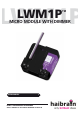
LWM1P LWM1P ™ MICRO MODULE WITH DIMMER USER MANUAL 3 LWM1P™ MICROMODULE WITH DIMMER 20259 / 20080521 © ALL RIGHTS RESERVED HAIBRAIN ®
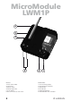
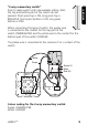
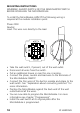
MicroModule LWM1P 6 5 4 3 ENGLISH 1.Phase clamp (230V) 2.Load clamp 3.Neutral clamps 4.Indicator light (LED) 5.Set up button 6.Wire connections to wall switch 2 2 1 NEDERLANDS 1.Fase aansluiting (230V) 2.Aansluiting voor belasting 3.Nullklemmen 4.LED indicator 5.Programmeerknopje 6.
SAFETY WARNINGS • The wiring of your electrical installation is live (230 V) and extremely dangerous. Never connect the module when plugged into the mains. Always turn off the main switch before starting the installation. • This product is for professional use and should be installed by a certified installer. • To prevent short circuits, this product should only be used inside and only in dry spaces. Do not expose the components to rain or moisture. Do not use the product close to a bath, swimming pool etc.
TABLE OF CONTENTS HOW DOES HAIBRAIN X-10 WORK? ADRESSES SIGNAL RANGE INSTRUCTIONS FOR USE INTRODUCTION FUNCTIONS MOUNTING INSTRUCTIONS PROGRAMMING USAGE OF THE MICROMODULES IN A 3 PHASE INSTALLATION TESTING THE FUSE LOW VOLTAGE HALOGEN LIGHTING FREQENTLY ASKED QUESTIONS TECHNICAL DATA 4 5 5 7 7 7 10 11 13 13 14 15 17 HOW DOES HAIBRAIN X-10 WORK? Haibrain X-10 components use the existing mains wiring to communicate (using Haibrain X-10 signals).
SIGNAL RANGE Range of Haibrain X-10 signals over the Power Line and how to increase the range. The Haibrain X-10 System is based on power line communication. The range of the Haibrain X-10 signals very much depends on the local circumstances. On average the range is a cable length of 80 meters. If you have difficulties with the range of your Haibrain X-10 signals, please pay attention to the following facts: 1.
from the power line, and testing the differences in range for your Haibrain system. When e.g. your conclusion is that e.g. your computer monitor is attenuating the signal, you can use a FM10 Plug-in Filter between the power line and the monitor to eliminate the effects. Known devices which can cause attenuation are: PC Monitors PCs with heavy internal power supplies Old Televisions Copiers Fluorescent Lights Gas Discharge Lamps (Energy Saving Lamps) 3.
INTRODUCTION Congratulations on the purchase of the Haibrain X-10 built-in dimmer module LWM1P. • Because of its extremely small proportions, the module can be built in behind wall switches and wall outlets (minimal backbox depth 40mm, advice 50mm). The module is also ideally suited to build in light armatures and for installation in small spaces in for instance lowered ceilings. • Multi-purpose: fully free choice in brand, colour and model switch material.
• Can respond to All Lights On and All Units Off (configuration). • Choice between 1-way momentary switch or 2-way momentary switch. Explanation about connecting switches: Note: In the standard setting the LWM1P module assumes a ‘2-way momentary switch’ has been connected. “1-way momentary switch”: Push to make switch without intermediate setting. 1 short press is ON, keeping the button pressed is DIM, second press is OFF.
ENGLISH “2-way momentary switch” Push to make switch with intermediate setting. Both the top and bottom part of the switch can be pressed. Short press top is ON, long press top is BRIGHTER. Short press bottom is OFF, long press bottom is DIM. When connecting this type of switch, the purple wire is connected to the contact for the top part of the switch (ON/BRIGHTER) and the white wire to the contact for the bottom part of the switch (OFF/DIM).
MOUNTING INSTRUCTIONS WARNING! ALWAYS SWITCH OFF THE MAIN MASTER SWITCH BEFORE INSTALLING THE MICROMODULE. To install the MicroModule LWM1P the following wiring is required at the module installation point. Phase 230V Neutral Load. This wire runs directly to the load. • • • • • • • • Take the wall switch, if present, out of the wall outlet. Disconnect all wires from the switch. Pull an additional N-wire in case this one is missing.
Activate the setup procedure. The following steps have to be taken to start the setup procedure for programming the MicroModule: • Press the setup (prog.) button for at least 3 seconds. The LED should stay on after releasing the setup button. • Warning! The MicroModule will leave the setup mode if it doesn’t receive any commands within 60 seconds. Exit setup mode • Press the setup button once shortly. You can also wait for at least 60 seconds so that the MicroModule will exit the setup mode automatically.
Programming the X10 address and the various options. The chart below shows the various possibilities to program the MicroModule LWM1P. Factory defaults Programmable Command Light blinks Address A1 Address A2 ..
NOTES: • When you program the MicroModule, always program the address first the optional functions second. • If the MicroModule receives a new address during setup mode, the optional functions will be automatically reset to the default settings. USAGE OF THE MICROMODULES IN A 3 PHASE INSTALLATION The X10 transmitters of the MicroModules transmit the command only once for use in the phase of which they are connected.
Replacing the fuse after melt-through. LWM1P LWM1P Replacing the fuse is possible without opening the module! (if the module has been opened the guarantee no longer applies). Remove the film above the fuse and then pull the fuse out of the module with pointed pliers. Replace the fuse with a fuse of one of the following types (with the application of other types the guarantee no longer applies): Supplier dimmer fuse Description Order number supplier Littelfuse LT-5 ALg 0663.01.
My modules will not respond to my controller. Make sure that the House Code on all Modules and Controllers are set to the same House Code (A .. P). My modules will not react to my remote / sensor. When you use a remote or sensor, you should have at least one TM13 Transceiver or Haibrain Security Console installed in your house. These components will translate the radio signals to the Haibrain X-10 signal on the power line.
Programming the LWM1P through the IRRF7243 is not working. If you wish to program the module with the help of a remote control and the IRRF7243 you need to follow a slightly different procedure (Example: setting UnitCode 2 with an 8in1 Multimedia remote control): • push the “house” on the remote control. • push button [2]. • give an [on] command 2 times. • close off with button [2]. The last action is only necessary when using the IRRF7243.
X-10 Key codes: X-10 transmisson: Switch use: Connection reach: Fuse: Environment temperature: Dimensions: Built-in depth: 230V ±10% - 50Hz. <30 mA capacitive 120W/230V light bulbs. 100W Low voltage halogen lighting with wound voltage transformer. 120W Low voltage halogen lighting with electronic voltage transformer. (recommended voltage transformer: Osram HTM series. If you use other voltage transformers, we advise you to test the combination before building in the system). Softstart/Softdim.