
- MARMITEK OWNER'S MANUAL VIDEO DOORPHONE


3. INSTALLATION
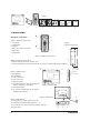
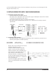
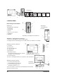
Description of the parts
Figure 2. Doorbell camera front
1. Screw hole
2. Loudspeaker
3. Camera
4. LEDs, for visibility in the dark
5. Bell button
6. Microphone
Figure 3. Doorbell camera back
7. Lugs for the attachment of sun/rain cover
8. 4-wire earthed power cable with connector for transfer of image and sound to monitor
Figure 4. Monitor front
9. Microphone
10. Loudspeaker
11. LCD screen 14cm
12. Power ‘On’ LED
13. Monitor button
14. Intercom button (for communication between
multiple monitors, if applicable)
15. Door-open button
16. On the side: sliders/wheels to set volume,
brightness and contrast
Figure 5. Monitor back
17. Connector for camera cable (R1 thru R4)
18. Connector for optional door opener (L+, L-)
19. On-Off switch 75 Ohm (usable for multiple monitors)
20. Power cable
4 © MARMITEK
Figure 1.
13 14 15
16
6
10
9
8
7
12
11
4
1
5
2
3
20
181719
Figure 2. Doorbell camera front
Figure 3.
Doorbell camera back
sliders/wheels
to set volume,
brightness
and contrast
Figure 4. Monitor front
Figure 5. Monitor back
1 2 3 4 5 6 7 8 9