
Mars N2 Unheated Series Submittal
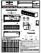
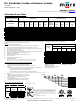
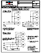
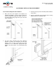
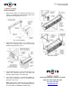
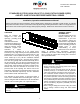
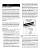
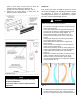
Table Of Contents
- N2 Unheated Submittals
- N2 Unheated Submittals Page 2
- BD14 Unhtd Sub Pkg
- PART 1 GENERAL
- 1.1 SECTION INCLUDES
- 1.2 RELATED SECTIONS
- A. Section 05 50 00 – Metal Fabrications: Concealed steel support members.
- B. Section 06 10 00 – Rough Carpentry.
- C. Section 05 41 00 – Structural Metal Studs.
- D. Section 07 62 00 – Sheet metal flashing.
- E. Section 07 92 00 – Joint Sealants.
- F. Section 08 10 00 – Metal Doors and Frames.
- G. Section 08 33 00 – Overhead Coiling Doors.
- H. Section 08 42 00 – Entrance Doors.
- I. Section 22 10 00 – Plumbing Piping:
- J. Section 23 21 00 – Hydronic Piping: Hot water heating piping to units.
- K. Section 23 22 13- Steam and Condensate Piping: Steam heating piping to units.
- L. Section 26 05 00 – Equipment Wiring: Connections to building power distribution.
- 1.3 REFERENCES
- A. ASTM A240 / A240M -10 – Standard Specification for Chromium and Chromium.
- B. ASTM A879 / A879M -06 – Standard Specification for Steel Sheet, Zinc Coated by the Electrolytic Process for Application Requiring Designation of the Coating Mass on Each Surface.
- C. ASTM A653 / A653M -09a – Standard Specification for Steel Sheet, Zinc Coated (Galvanized) or Zinc-Iron Alloy-Coated (Galvannealed) by the Hot-Dip Process.
- D. UL 507 – UL Standard for Safety Electric Fans – Intertek Testing Services Listed for US and Canada.
- E. UL508A – Standard for Industrial Control Panels
- F. UL 1995/CSA 22.2 – UL Standard for Safety Heating and Cooling Equipment – Intertek Testing Services Listed for US and Canada.
- G. UL 2021/CSA 22,.2 – Standard for Fixed and Location-Dedicated Electric Room Heaters – Intertek Testing Services Listed for US and Canada.
- H. AHRI 410-2001 – Standard for Forced-Circulation Air-cooling and Air-Heating Coils.
- I. NSF/ANSI 37 – Air Curtains for entranceways in food and food service establishments – ETL Sanitation.
- J. AMCA 211 (Air Movement & Control Association International, Inc.) – Certified Ratings Program – Product Rating Manual for Fan Air Performance.
- K. CEC – Approved Elec heating Coils
- L. Electrical components UL/CUL listed.
- M. NEC – National Electric Code.
- N. U.S. Green Building Council, LEED Building Design and Construction (BD+C) Version 4.0 Rating System. (LEED v4.0).
- 1.4 SUBMITTALS
- A. Submit under provisions of Section 01 33 00.
- B. Product Data: Manufacturer's data sheets on each product to be used, including:
- C. Shop Drawings: Include plans, elevations, sections, and details, indicating dimensions, tolerances, materials, fasteners, hardware, finish, piping, electrical wiring diagrams, options, and accessories.
- D. LEED Submittals: Provide documentation of how the requirements of Credit will be met:
- 1. List of proposed materials with recycled content. Indicate post-consumer recycled content and pre-consumer recycled content for each product having recycled content.
- 2. Product data and certification letter indicating percentages by weight of post-consumer and pre-consumer recycled content for products having recycled content.
- E. Selection Samples: For each finish product specified, two complete sets of color chips representing manufacturer's full range of available colors and patterns.
- F. Verification Samples: For each finish product specified, two samples, minimum size 6.25 inches (160 mm) square, representing actual product, color, and patterns.
- G. Manufacturer's Certificates: Certify products meet or exceed specified requirements.
- H. Operation and Maintenance Manual: Submit manufacturer's operation and maintenance manual, including operation, maintenance, adjustment, and cleaning instructions, trouble shooting guide, parts list, and electrical wiring diagrams.
- 1.5 QUALITY ASSURANCE
- 1.6 DELIVERY, STORAGE, AND HANDLING
- 1.7 SEQUENCING
- A. Ensure that locating templates and other information required for installation of products of this section are furnished to affected trades in time to prevent interruption of construction progress.
- B. Coordinate the installation of wiring and control switches for air curtains with the openings and the hardware provided for such openings.
- C. Install after doors, walls, ceilings, and other adjacent surfaces are finished and painted.
- 1.8 WARRANTY
- PART 2 PRODUCTS
- 2.1 MANUFACTURER
- A. Acceptable Manufacturer: Mars Air Systems, LLC; 14716 South Broadway St., Gardena, CA 90248. Tel: (310) 532-1555 or (800) 421-1266. Fax: (310) 324-3030. Email: info@marsair.com. Web: www.marsair.com.
- B. Delete one of the following two paragraphs: coordinate with requirements of Division 1 section on product options and substitutions.
- C. Requests for substitutions will be considered in accordance with provisions of Section 01 33 00.
- 2.2 AIR CURTAIN ASSEMBLIES
- A. Motor Fan Assembly: Design for easy removal, assembly, repair, and maintenance.
- 1. Motor: Totally enclosed air over (TEAO) cooled motor with sealed lifetime pre-lubricated ball bearings, motor starter and thermal overload protection.
- a. Wired for single speed operation.
- b. Wired for two speed operation. (Not Applicable for Fly Insect Control Unit)
- c. Wired for three speed operation. (Not applicable for Fly Insect Control Unit)
- d. Provide wash down type motors, NEC IP-54 for the locations indicated.
- e. Provide explosion proof type motors, NEC Class 1, Division 1, Group D for the locations indicated.
- f. Electrical Characteristics: 115V AC, single phase; 5.1 Amp full load per motor/fan.
- g. Electrical Characteristics: 208/230V AC, single phase; 2.5 Amp full load per motor/fan.
- h. Electrical Characteristics: 208/230V AC, three-phase; 1.8/1.6 Amp full load per motor/fan.
- i. Electrical Characteristics: 460V AC, three-phase; 0.8 Amp full load per motor/fan.
- j. Electrical Characteristics: 575V AC, three-phase; 0.65 Amp full load per motor/fan.
- k. Meets NEC. ETL Listed to conform to UL 507 (US) and CSA22.2 (Canada) Standards. AMCA 211 Certified.
- 2. Fans: Forward curved centrifugal type, double width, and double inlet design, directly driven to an electric motor.
- 1. Motor: Totally enclosed air over (TEAO) cooled motor with sealed lifetime pre-lubricated ball bearings, motor starter and thermal overload protection.
- B. Housing: Self-contained one-piece type with sufficient strength for mounting from pre-punched mounting holes at both ends to adjacent walls or ceiling without intermediate support.
- 1. Size:
- a. Unheated: 12-3/4 inches deep by 10-5/8 inches high (including discharge nozzle) by width of unit.
- b. Electric Heated: 17-3/8 inches deep by 10-5/8 inches high (including discharge nozzle) by width of unit.
- c. Hot Water/Steam Heated: Depth 17-3/8 inches single row and double row by 10-5/8 inches high including discharge nozzle by width of unit plus 10 inches for manifolds.
- 2. Mounting:
- 3. Material:
- 4. Air Inlet Grille and/or Filters: Provide air inlet grille and/or filters specified.
- 5. Discharge: Provide integral discharge nozzle specified.
- 6. Finish and Color: Provide with, no VOC, corrosion resistant polyurethane powder coated finish for sheet metal housings.
- 1. Size:
- C. Environmental Air Curtains: Models for Heights to 12 feet (3656 mm) for Environmental Separation and Temperature Control and up to 10 feet (3048 mm) for Flying Insect Control (STD2 series)
- 1. Discharge Nozzle: Wedge-shaped discharge outlet nozzle with adjustable air foil vanes with a plus/minus 40-degree sweep front to back.
- 2. Air Velocity at Nozzle:
- a. STD236-1: 36 Inch (915 mm) Wide Units: 2206 feet/min (11.2 m/s) single 1/2HP motor/fan assembly.
- b. STD242-1: 42 Inch (1065 mm) Wide Units: 1945 feet/min (9.9 m/s) single 1/2HP motor/fan assembly.
- c. STD248-1: 48 Inch (1220 mm) Wide Units: 1730 feet/min (8.8 m/s) single 1/2HP motor/fan assembly.
- d. STD260-2: 60 Inch (1524 mm) Wide Units: 2592 feet/min (13.2 m/s) single 1/2HP motor/fan assembly.
- e. STD272-2: 72 Inch (1830 mm) Wide Units: 2206 feet/min (11.2 m/s) two 1/2HP motor/fan assemblies.
- f. STD284-2: 84 Inch (2133 mm) Wide Units: 1945 feet/min (9.9 m/s) two 1/2HP motor/fan assemblies.
- g. STD296-2: 96 Inch (2440 mm) Wide Units: 1730 feet/min (8.8 m/s) two 1/2HP motor/fan assemblies.
- h. STD2108-3: 108 Inch (2743 mm) Wide Units: 2206 feet/min (11.2 m/s) two 1/2HP motor/fan assemblies.
- i. STD2120-3: 120 Inch (3050 mm) Wide Units: 2084 feet/min (10.6 m/s) three 1/2HP motor/fan assemblies.
- j. STD2144-3: 144 Inch (3660 mm) Wide Units: 1730 feet/min (8.8 m/s) three 1/2HP motor/fan assemblies.
- 3. Air Speed at Floor: Minimum of 300 fpm (1.53 m/s) at 3 feet (914 mm) from the floor.
- 4. Air Inlet Grille and Filters:
- 5. Sound Pressure Level At 10 feet (3 m) From Nozzle:
- D. Insect Control Air Curtains: Models for Heights up to 7 feet (3048 mm) for Flying Insect Control. Certified to NSF/ANSI Standard 37. (N2 Series)
- 1. Discharge Nozzle: Wedge-shaped discharge outlet nozzle with adjustable air foil vanes with a plus/minus 40-degree sweep front to back.
- 2. Air Velocity at Nozzle:
- a. N236-1: 36 Inch (915 mm) Wide Units: 2206 feet/min (11.2 m/s) single 1/2HP motor/fan assembly.
- b. N242-1: 42 Inch (1065 mm) Wide Units: 1945 feet/min (9.9 m/s) single 1/2HP motor/fan assembly.
- c. N248-1: 48 Inch (1220 mm) Wide Units: 1730 feet/min (8.8 m/s) single 1/2HP motor/fan assembly.
- d. N260-2: 60 Inch (1524 mm) Wide Units: 2592 feet/min (13.2 m/s) single 1/2HP motor/fan assembly.
- e. N272-2: 72 Inch (1830 mm) Wide Units: 2206 feet/min (11.2 m/s) two 1/2HP motor/fan assemblies.
- f. N284-2: 84 Inch (1830 mm) Wide Units: 1945 feet/min (9.9 m/s) two 1/2HP motor/fan assemblies.
- g. N296-2: 96 Inch (2440 mm) Wide Units: 1730 feet/min (8.8 m/s) two 1/2HP motor/fan assemblies.
- h. N2108-3: 108 Inch (2743 mm) Wide Units: 2206 feet/min (11.2 m/s) two 1/2HP motor/fan assemblies.
- i. N2120-3: 120 Inch (3050 mm) Wide Units: 2084 feet/min (10.6 m/s) two 1/2HP motor/fan assemblies.
- j. N2144-3: 144 Inch (3600 mm) Wide Units: 1730 feet/min (8.8 m/s) two 1/2HP motor/fan assemblies.
- 3. Air Speed at Floor:
- 4. Air Inlet Grille and Filters:
- 5. Sound Pressure Level At 10 feet (3 m) From Nozzle:
- A. Motor Fan Assembly: Design for easy removal, assembly, repair, and maintenance.
- 2.3 COMPONENTS
- A. Electric Heaters: Provide complete with motor control panel factory mounted to air curtain housing, and thermostat to be field installed
- 1. Temperature limit controller.
- 2. Thermostat: Wall-mounted, 24-Volt operation, with heater on/off selection.
- 3. Heating Coils: ETL approved as part of unit. Meets NEC and CEC tested by ETL Certified to conform to UL2021(US) and CSA22.2 (Canada) Standards. Factory mounted on the discharge end of the motor fan assembly and located within the nozzle outlet.
- B. Steam Heaters: Provide finned tube steam coils for field mounting on air intake side of the air curtain cabinet with opposite end connections.
- 1. Meets NEC and CEC tested by ETL Certified to conform to UL1995(US) and CSA22.2 (Canada) Standards.
- 2. Output: Air curtain manufacturer's standard, one-row coils.
- 3. Coils: Certified in accordance with AHRI 410.
- 4. Connections: Opposite end.
- 5. Connections: Same end, right hand.
- 6. Connections: Same end, left hand.
- 7. Casing: One-piece unpainted galvanized steel, bolted to air curtain housing.
- 8. Supply and return fittings on ends of casing.
- 9. Steam Distributing coil required for 8 feet and above for same end coils. Dual supply, Single returns.
- 10. Thermostat: Wall-mounted, 110-Volt operation, with heater on/off selection.
- 11. Thermostat: Wall-mounted, 208/230-Volt operation, with heater on/off selection.
- C. Hot Water Heaters: Provide finned tube water coils for field mounting on air intake side of the air curtain cabinet with opposite end connections.
- 1. Meets NEC and CEC tested by ETL Certified to conform to UL1995(US) and CSA22.2 (Canada) Standards.
- 2. Output: Air curtain manufacturer's standard, one-row coils.
- 3. Output: Air curtain manufacturer's standard, two-row coils.
- 4. Coils: Certified in accordance with AHRI 410.
- 5. Connections: Opposite end.
- 6. Connections: Same end, right hand.
- 7. Connections: Same end, left hand.
- 8. Casing: One-piece unpainted galvanized steel, bolted to air curtain housing.
- 9. Supply and return fittings on top of casing.
- 10. Thermostat: Wall-mounted, 110-Volt operation, with heater on/off selection.
- 11. Thermostat: Wall-mounted, 208/230-Volt operation, with heater on/off selection.
- D. Motor Control Panels for Unheated Units: Recommended for all three-phase units and single phase units with combined motor capacities of more than 1 HP whenever a door limit switch is used to automatically start and stop the air curtain. Provide mot...
- 1. Mounting: Shipped loose to be field mounted.
- 2. Mounting: Factory mounted on right hand side of air curtain housing.
- 3. Mounting: Factory mounted on left hand side of air curtain housing.
- 4. Electrical components UL/CUL listed.
- 5. Panels UL 508A listed.
- 6. Optional Digital Programmable Controller:
- a. Remote Mounted High Resolution 5” Color LCD Display with Capacitive Touch technology
- b. Fully programmable controller
- c. Pre-set and fully customizable programs
- d. Time delay (Passive & Adaptive)
- e. 24/7 timer
- f. Maintenance schedule alerts
- g. Status display showing date, time, temperature, and air curtain mode
- h. Multi-unit control capability
- i. English (IP) or Metric (SI) display readings
- j. Password protected
- k. Auto Lock display
- l. Emergency shut-off button
- m. Low voltage control signal for door activation
- n. Integrated BMS controls
- o. VFD compatible with 0-10VDC output
- p. Optional BACnet option
- q. Optional adaptive fan speed control based on existing field conditions. Field mounted outdoor temperature sensors required.
- E. Motor Control Panels for Electric Heated Units: Recommended for all three-phase units and single-phase units with combined motor capacities of more than 1 HP whenever a door limit switch is used to automatically start and stop the air curtain. Moto...
- 1. Mounting: Factory mounted on the inside of air curtain housing.
- 2. Mounting: Factory mounted on left hand side of air curtain housing.
- 3. Electrical components UL/CUL listed.
- 4. Optional Digital Programmable Controller:
- a. Remote Mounted High Resolution 5” Color LCD Display with Capacitive Touch technology
- b. Fully programmable controller
- c. Pre-set and fully customizable programs
- d. Time delay (Passive & Adaptive)
- e. Factory Integrated temperature control sensors. No external thermostat required.
- f. Summer-Winter modes
- g. 24/7 timer
- h. Maintenance schedule alerts
- i. Status display showing date, time, temperature, and air curtain mode
- j. Multi-unit control capability
- k. English (IP) or Metric (SI) display readings
- l. Password protected
- m. Auto Lock display
- n. Emergency shut-off button
- o. High temperature lock from fan failure
- p. Low voltage control signal for door activation
- q. Integrated BMS controls
- r. VFD compatible with 0-10VDC output
- s. Optional BACnet option
- t. Optional adaptive fan speed control and heat control based on existing field conditions. Field mounted outdoor temperature sensors required.
- F. Motor Control Panels For Hot Water, Steam and Gas Heated Units: Recommended for all three-phase units and single phase units with combined motor capacities of more than 1HP whenever a door limit switch is used to automatically start and stop the ai...
- 1. Mounting: Shipped loose to be field mounted.
- 2. Mounting: Factory mounted on right hand side of air curtain housing.
- 3. Mounting: Factory mounted on left hand side of air curtain housing.
- 4. Provide with remote mount thermostat for field installation.
- 5. Electrical components UL/CUL listed.
- 6. Optional Digital Programmable Controller:
- a. Remote Mounted High Resolution 5” Color LCD Display with Capacitive Touch technology
- b. Fully programmable controller
- c. Pre-set and fully customizable programs
- d. Time delay (Passive & Adaptive)
- e. Factory Integrated temperature control sensors. No external thermostat required.
- f. Summer-Winter modes
- g. 24/7 timer
- h. Maintenance schedule alerts
- i. Status display showing date, time, temperature, and air curtain mode
- j. Multi-unit control capability
- k. English (IP) or Metric (SI) display readings
- l. Password protected
- m. Auto Lock display
- n. Emergency shut-off button
- o. High temperature lock from fan failure
- p. Low voltage control signal for door activation
- q. Integrated BMS controls
- r. VFD compatible with 0-10VDC output
- s. Optional BACnet option
- t. Optional adaptive fan speed control and heat control based on existing field conditions. Field mounted outdoor temperature sensors required.
- G. Door-Activated Limit switch(s): Provide, field installed 250-Volts, 20 amps limit switch to control air curtain(s) as follows; Automatic on/off control, activates air curtain when door is opened and turns off when door is closed. Provide limit swit...
- 1. Type: Combination plunger/roller switch for swing and sliding doors.
- a. Provide limit switches with NEMA 1 (20 amps) ratings in locations indicated.
- b. Provide limit switches with NEMA 4X (10 amps) ratings in locations indicated.
- c. Provide limit switches with NEMA 4X (15 amps) ratings in locations indicated.
- d. Provide limit switches with NEMA 7 (10 amps) ratings in locations indicated.
- 2. Type: Magnetic reed switch and actuator for swing and sliding doors. Industrial floor mounted or surface mounted switches for roll up doors.
- 3. Operation for Unheated Units: Automatic on/off control, on when door is opened, off when door is closed.
- 4. Operation for Heated Units: Automatic on when door is opened, off after time delay period after door is closed, maintaining heat in the event door is opened within time delay period. Field adjustable from 1 to 17 minutes.
- 1. Type: Combination plunger/roller switch for swing and sliding doors.
- H. Provide mounting hardware as required for the opening.
- A. Electric Heaters: Provide complete with motor control panel factory mounted to air curtain housing, and thermostat to be field installed
- 2.1 MANUFACTURER
- PART 3 EXECUTION
- 3.1 EXAMINATION
- A. Verify that required utilities are in correct location and are of correct capacities for specified products.
- B. Verify openings to receive air curtains are plumb, level, square, accurately aligned, correctly located, and in tolerance.
- C. Examine surfaces to receive air curtains. If surface preparation is the responsibility of another installer, notify Architect of unsatisfactory preparation before proceeding.
- 3.2 INSTALLATION
- A. Install air curtains in accordance with approved shop drawings and manufacturer's printed installation instructions.
- B. Install air curtains plumb, level, square, true to line, and weathertight, without warp or rack.
- C. Anchor air curtains securely in place to supports.
- D. Coordinate with sheet metal flashing as specified in Section 07 62 00.
- E. Install joint sealants as specified in Section 07 92 00.
- F. Coordinate with electrical power as specified in Section 26 05 00.
- G. Install door limit switches and adjust for correct operation.
- H. Provide connection to piped services and utilities as specified in Section 22 10 00 and 23 21 00.
- 3.3 FIELD QUALITY CONTROL
- A. Adjust air curtains to function properly.
- B. Adjust air foil vanes located within the discharge nozzle as required for prevailing conditions at each opening.
- C. Check heated air curtain performance on a calm day by measuring air temperature 6 inches off the floor. Optimal reading is halfway between the temperature inside and outside the building.
- 3.4 CLEANING
- A. Clean air curtains promptly after installation in accordance with manufacturer's instructions.
- B. Repair minor damages to finish in accordance with manufacturer's instructions and as approved by Architect.
- C. Remove and replace damaged components that cannot be successfully repaired as determined by Architect.
- 3.5 PROTECTION
- 3.6 SCHEDULES
- 3.1 EXAMINATION

N2 (Sanitation Customer Entrance) Series
Unheated
Model Lengths 36” – 144”
14716 S. BROADWAY, GARDENA, CA 90248 ● Ph: (310)532-1555 Fax: (310)-532-3030 ● www.marsair.com
© Copyright Mars Air Systems, LLC 2014
NOTE: MARS AIR SYSTEMS, LLC reserves the right to change specifications and product design without notice. Such revisions do not entitle the buyer to corresponding changes, improvements, additions, or replacements
for previously purchased equipment.
MARS AIR SYSTEMS, LLC ● GARDENA, CA ● USA VM, 09/15/20
1. The AMCA Certified Ratings Seal applies to airflow rate, average outlet velocity, outlet velocity uniformity, velocity projection and power rating at free delivery only.
2. Rated data shown are only for base (unheated) units, as shown.
115v/1Ø
(A)
208-230v/1Ø
(D)
208-230v/3Ø
(G)
460v/3Ø
(H)
575v/3Ø
(I)
N236-1U*-OB
5.1 2.5 1.8/1.6 0.8 0.7
N242-1U*-OB 5.1 2.5 1.8/1.6 0.8 0.7
N248-1U*-OB 5.1 2.5 1.8/1.6 0.8 0.7
N260-2U*-OB 10.2 5.0 3.6/3.2 1.6 1.4
N272-2U*-OB 10.2 5.0 3.6/3.2 1.6 1.4
N284-2U*-OB 10.2 5.0 3.6/3.2 1.6 1.4
N296-2U*-OB 10.2 5.0 3.6/3.2 1.6 1.4
N2108-3U*-OB 15.3 7.5 5.4/4.8 2.4 2.1
N2120-3U*-OB 15.3 7.5 5.4/4.8 2.4 2.1
N2144-3U*-OB 15.3 7.5 5.4/4.8 2.4 2.1
Alternate voltage codes with FLA (Full Load Amp) data:
277v/1Ø/60Hz (L) - 2.7A per motor 380-415v/3Ø/50Hz (W) - 1.1A per motor
220v/1Ø/50Hz (U) - 2.5A per motor
For total FLA, multiply motor FLA by # of motors.
Ampacity (MCA) = total FLA X 1.25
* - Use corresponding letters in"Electrical Data" columns to complete the model numbers.
Unit Voltage (Voltage Code)
Electrical Data
(FLA)
Single Phase
Three Phase
N2
Series: N 2
72 2
U
D
TS
LENGTH OF UNIT
# OF MOTORS
U = UNHEATED
VOLTAGE CODE
COLOR
EXAMPLE
MARS Air Systems, LLC certifies that the Air Curtains shown on this data
sheet are licensed to bear the AMCA seal. The ratings shown are based on
tests and procedures performed in accordance with AMCA Publication 211
and comply with the requirements of the AMCA Certified Ratings Program.
The AMCA Certified Ratings Seal applies to airflow rate, average outlet
velocity, outlet velocity uniformity, velocity projection and power rating at
free delivery only.
Note: Model N260-2 is not AMCA Certified.
Unheated Data Sheet
Applications: Insect Control (up to 7’)
Features:
1/2 HP Continuous Duty TEAO Motors
Sleek self-contained one-piece heavy gauge corrosion proof paint lock metal design
ETL Certified to conform to ANSI/NSF 37 Standards for Customer Entrances up to 7’
ETL Certified to conform to UL 507 (US) and CSA 22.2 (Canada) Standards (Indoor/Outdoor Use)
AMCA Certified to AMCA 211 Standards
Top and wall mounting holes provided (7/16”)
Cabinet has sufficient strength for fastening to wall on both ends without intermediate support.
Adjustable air directional vanes with 40° sweep front to back
Standard color is Obsidian Black
Rust preventative electrostatic polyurethane powder coating
5-year parts warranty
Freight Included (FOB Continental USA)
Proudly Made in the USA
Note: All N2 (1) motor units are shipped with the Motor Fan Assembly (MFA) factory installed inside
the air curtain housing. For all other models, the MFA are shipped loose to minimize freight damage
Mars Recommended Accessories (See Submittals for additional details):
Door Limit Switches
o 99-014, Combination mechanical switch, 250v, 1HP Max
o 99-125, Industrial surface mounted magnetic switch (controller required)
Controllers
o MCPA-†U*, Motor Control Panel, 120V control voltage († = # of Motors, * = Voltage Code)
o MCP-TD, Adjustable time delay, 1sec-100hr (panel required)
o MCP-24V, Low voltage control option (panel required)
o BMS-303, BMS for monitor and control (panel required with MCP-24V)
Note: Dry contact provided in panel for monitoring motor. 24Vac signal provided from panel for controlling motor
Brackets
o B0004, Adjustable mounting bracket set, 3 ½” clearance
o B0005, Adjustable mounting bracket set, 7”-13” clearance
o B0041, Transom mounting bracket set for STD2
Severe Duty and Finish
o HSG-304SS-STD, 304 Stainless steel housing construction
o INS-WD-STD2, Washdown motor fan assembly, IP54
Sound Levels: (measured at 10’ in an open field)
1 Motor Unit = 66 dBA, 2 Motor Unit = 68 dBA, 3 Motor Unit = 71 dBA & 4 Motor Unit = 73 dBA
N2
(Sanitation Customer Entrance)
Series 2
Model Number
Nozzle Length
(in)
Length
(in)
Depth
(in)
Height
(in)
Motor
(hp)
Weight
(lbs)
Max Core
Velocity at
Nozzle (fpm)
Avg Velocity
(fpm)
Volume
(cfm)
Uniformity
(%)
Power Rating
(watts)
N236-1U*-OB 36 36 13 11 1/2 60 5960 2206 1379 84 500
N242-1U*-OB 42 42 13 11 1/2 65 4865 1945 1418 87 510
N248-1U*-OB 48 48 13 11 1/2 70 4247 1730 1442 85 550
N260-2U*-OB 60 60 13 11 Two 1/2 90 6737 2592 2700 93 940
N272-2U*-OB 72 72 13 11 Two 1/2 120 5960 2206 2758 84 1000
N284-2U*-OB 84 84 13 11 Two 1/2 125 4865 1945 2836 87 1020
N296-2U*-OB 96 96 13 11 Two 1/2 135 4247 1730 2884 85 1100
N2108-3U*-OB 108 108 13 11 Three 1/2 175 5960 2206 4137 84 1500
N2120-3U*-OB 120 120 13 11 Three 1/2 185 4660 2084 4341 92 1570
N2144-3U*-OB 144 144 13 11 Three 1/2 200 4247 1730 4326 85 1650
Mechanical Data
Note: ETL Sanitation models available in 60 Hz only.
AMCA Certified Lab Data
* - Use corresponding letters in "Electrical Data" columns to complete the model numbers.
Model
Distance from
nozzel (in)
Avg. Core Velocity
(FPM)
40 1207
80 856
120 710
160 637
200 588
Projection Velocity
N236-1U*