Marshall Electronics NCB-1004 Network Control Box for IMD Monitors Operating Instructions
Contents Product Overview.................................................................................................................................................................. 4 Features ................................................................................................................................................................................. 4 Installation and Initial Setup ......................................................................................................
Product Overview The NCB-1004 Network Control box is a comprehensive remote control solution for Marshall’s IMD (In-Monitor Display) line of monitors. The NCB-1004 offers complete control of each monitor's menu settings and adjustments such as contrast, color, curtain color, aspect ratio, and more. The NCB-1004 can control up to 256 monitors individually by ID#, or up to 512 monitors simultaneously on a global scale.
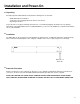
Installation and Power-On ■ Unpacking Carefully unpack the NCB-1004 and verify that the following items are included: • NCB-1004 Network Control Box • V-PS12-5V-1 Power Supply with 2-Pin Twist Lock Connector • Operating Instructions Inspect the unit for any physical damage that may have occurred during shipping. Should there be any damage, immediately contact Marshall Electronics at (800) 800-6608. If you are not located within the continental United States, call +1 (310) 333-0606.
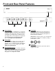
Front and Rear Panel Features RS-422 Outputs The RS-422 outputs send MEI protocol commands to Marshall’s IMD line of monitors. Each output has exactly the same signal. Up to 128 screens can be connected to each output. These output ports also pass Image Video or TSL v4.0 protocol commands from the Control Input, embedded in the MEI protocol. See Page 22 for specifications. Control Input The RS-422 Control Input receives Image Video or TSL v4.0 protocol commands from an external controller.
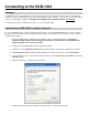
Connecting to the NCB-1004 Overview The NCB-1004 can be operated by any computer with a web browser, via a TCP/IP network connection. No additional software is needed. The NCB-1004 may be connected directly to a single computer, or connected to a local area network and accessed by multiple computers. The NCB-1004 is shipped with the default IP address 192.168.0.233. The following procedures describe the two ways to connect to the NCB-1004.
Connecting to the NCB-1004 (continued) Connecting the NCB-1004 to a Single Computer (continued) 8. Click OK in the Internet Protocol (TCP/IP) Properties window, and then click Close in the Local Area Connection Properties window. 9. Open any web browser application (Internet Explorer, Firefox, etc.) 10. Enter the address http://192.168.0.233/ 11. Click OK if the following dialog appears: 12. If successfully connected, the web interface of the NCB-1004 will be shown in the browser windows as shown below.
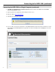
Connecting to the NCB-1004 (continued) Connecting the NCB-1004 to a Local Area Network If the network portion of the unit’s IP address (first three numbers) matches your network, the NCB-1004 can be connected to a local area network and accessed from any computer on the network. The unit’s IP address must also be available on the network and reserved for the NCB-1004. 1.
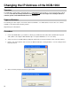
Changing the IP Address of the NCB-1004 Overview The NCB-1004 is shipped with a default IP address of 192.168.0.233. This IP address can be changed via the network connection. Note that the existing IP address must be known to make this change. If the existing IP address is unknown, please contact Marshall Electronics for assistance. Required Software The following procedure requires Tera Term software for Windows, or a similar SSH tool.
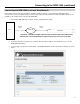
Changing the IP Address of the NCB-1004 (continued) Procedure (continued) 5. At the password prompt shown below, do not enter a password and simply click OK: 6. Then, the following command line interface should appear: 7.
Changing the IP Address of the NCB-1004 (continued) Procedure (continued) 8. The following file information should appear: 9. This file must be edited to save the new IP address. Use the following commands to edit the file. Edit only the numbers. Do not press the enter key after each command.
System Configuration Overview The NCB-1004 can be used in three different system configurations. The following diagrams show the different configurations: Basic Remote Control of IMD Monitors ■ Overview Use the following configuration for basic remote control of Marshall IMD series monitors. This setup allows remote control of all features in the on-screen menu of each IMD monitor. ■ Wiring Diagram Use the following configuration for basic remote control of Marshall IMD series monitors.
System Configuration (continued) Remote Control with Image Video Pass-Through ■ Overview Use the following configuration for basic remote control of Marshall IMD series monitors, while also passing through Image Video protocol. This setup allows remote control of the IMD monitor, and pass-through of Image Video text and tally commands from an Image Video TSI-1000 or other Image Video protocol source.
System Configuration (continued) Remote Control with TSL Pass-Through ■ Overview Use the following configuration for basic remote control of Marshall IMD series monitors, while also passing through TSL v4.0 protocol. This setup allows remote control of the IMD monitor along with pass-through of TSL text and tally commands from a TSL Tally Man controller or other TSL protocol source.
Web Interface Overview The web interface is used to operate the NCB-1004. Once the NCB-1004 is connected to a network, access the web interface by entering the units IP address in any web browser on any computer on the network. The web interface allows remote control of all on-screen menu features of individual monitors or all monitors connected. The web interface also controls the pass-through of Image Video or TSL protocol.
Web Interface (continued) Window Management The Window Management page is shown below: Use the buttons and menus shown above for the following settings: o o o o o Aspect Ratio (4:3, Scaled 4:3, 16:9, Centered 16:9 / Full Screen) On-Screen Markers (Aspect Ratio and Safe Area Markers) Center Marker Marker Background Curtain Color Key & Image Enhancement The Key & Image Enhancement page is shown below: Use the buttons and menus shown above for the following settings: o o o o Keypad Commands (Menu, Select,
Web Interface (continued) Preset Configuration The Preset Configuration page is shown below: Use the buttons shown above to load and save presets in each monitor. Note that these controls affect the presets in each monitor only. There are no presets in the NCB-1004 itself.
Web Interface (continued) OSD Configuration & IMD The OSD Configuration & IMD page is shown below: Use the first section of the OSD & IMD page to set the protocol pass-through settings: o o o o Set Protocol (Image Video, TSL) – Select the protocol type to be passed through the NCB-1004. Note that this option must be set according to the protocol that is applied to the Control In input on the NCB-1004. Pass-Through (On, Off) – Enable or disable the pass-through of Image Video or TSL protocol.
Web Interface (continued) System The System page is shown below: Use the buttons shown above to send the following commands: o o o o o o o o Ping (Healthy, Unhealthy) – Test a command and response with a monitor. Get Software Version – Reads the main software version of a monitor. Get Protocol Version – Reads the protocol version of a monitor. Get Keypad Version – Reads the keypad software version of a monitor Get Model Number – Reads the model number of a monitor.
Web Interface (continued) Table of Web Interface Commands Window Management Aspect Ratio Set Marker Set Center Set Background Set Curtain Color Menu Controls Color Key & Image Enhancement Preset Configuration Test Mode Main OSD Configuration & IMD System Brightness Contrast Color Temp Load Save Reset Test Mode Blue Only Monochrome Pixel-to-Pixel Set Protocol Pass-Through Protocol Type TSL Status IMD State Status Display Timecode Audio Monitor Show IMD Address Set IMD Inensity Send IMD Alignment Sen
Specifications ■ CONTROL INPUT ■ NETWORK CONNECTION Connector 1 x RJ12 (Modular 6P6C) Connector 1 x RJ45 (Modular 8P8C) Physical Layer RS-422 Physical Layer 10BASE-T or 100BASE-T Ethernet Data Protocols Image Video: Start Bits Data Bits Parity Stop Bits Baud Rate Data Protocol TCP/IP 1 7 Even 1 38400 TSL v4.0 Protocol: Start Bits Data Bits Parity Stop Bits Baud Rate 1 8 Even 1 38400 Pinout Pin No. 1 2 3 4 5 6 ■ ELECTRICAL Power Consumption Voltage Requirement 3.
Specifications (continued) Warranty Marshall Electronics warranties to the first consumer that this NCB-1004 LCD monitor will, under normal use, be free from defects in workmanship and materials, when received in its original container, for a period of one year from the purchase date. This warranty is extended to the first consumer only, and proof of purchase is necessary to honor the warranty.
Marshall Electronics, Inc. 1910 East Maple Ave. El Segundo, CA 90245 Tel: (800) 800-6608 / (310) 333-0606 • Fax: 310-333-0688 www.LCDRacks.com • sales@lcdracks.