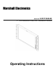
Marshall Electronics Model No.
This page intentionally left blank 2
Contents Features................................................................................................................................................................ 4 Installation and Initial Setup ........................................................................................................................... 5 Unpacking .....................................................................................................................................................................
Features The DLW (Dual Link / Waveform) Series is the latest addition to Marshall's expanding line of IMD-equipped monitors. ■ 1920 x 1200 Full Resolution 17” Panel The V-R171X-DLW features an all-digital TFT-MegaPixel active matrix LCD system with 1920x1200 native resolution. 2 The LCD panel features a brightness of 500 cd/m and a 800:1 contrast ratio making it ideal in a variety of environments and lighting conditions.
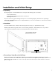
Installation and Initial Setup ■ Unpacking Carefully unpack the V-R171X-DLW monitor and verify that the following items are included: • V-R171X-DLW Monitor • V-PS12-5V-1 Power Supply with Twist-Lock Connector • Operating Instructions Inspect the unit for any physical damage that may have occurred during shipping. Should there be any damage, immediately contact Marshall Electronics at (800) 800-6608. If you are not located within the continental United States, call +1 (310) 333-0606.
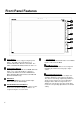
Front Panel Features Power Button Turn the monitor off or on by pressing the power button. The LED on the power button is at maximum illumination when the unit is OFF. The LED is at minimum illumination when the unit is on. Input Channel Buttons Pressing SDI 1 or SDI 2 will select HDSDI-SDI Video Inputs 1 or 2, respectively. When a channel is activated, the LED on the channel will illuminate. When displaying Dual Link formats, both LEDs will illuminate simultaneously.
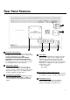
Rear Panel Features RS-422/485 Serial Interface The RS-422/485 ports are used to remotely control the IMD or all V-R171X-DLW features, using a variety of industry standard protocols. (Note: Connector/pin-out may need to be adapted depending on protocol and controlling device used.) Only one connection to either port is needed to control the monitor. The second port can be used to loop multiple monitors in the same bus.
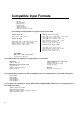
Compatible Input Formats The following SDI standards are supported by the V-R171-DLW: 525i, 625i 720p (60, 59.94, 50) 720p (30 / 29.97) 1035i (60 / 59.94) 1080i (60 / 59.94 / 50) 1080psF (24 / 23.98) 1080p (30 / 29.97 / 25 / 24 / 23.98) The following 3G-SDI standards are supported by the V-R171-DLW 1080p (60 / 59.94 / 50) 1080p (30 / 29.97 / 25 / 24 / 23.
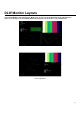
DLW Monitor Layouts The V-R171X-DLW has 4 possible layouts, Multi mode, Vectorscope mode, Waveform mode and Full Screen Video mode. Each press of the LAYOUT Button will change the current mode to next available mode.
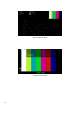
Waveform Monitor Mode Full Screen Video Mode 10
On-Screen Menu STRUCTURE OVERVIEW 11
On-Screen Menu (continued) MAIN MENU AND NAVIGATION Access and navigate the main menu using the RotoMenu™ knob: Main Menu Using the RotoMenu knob • Press the RotoMenu™ knob to enter the main menu. • Rotate the knob to scroll up or down in the main menu or each submenu. • Press the RotoMenu™ knob to enter a submenu or choose a setting. • To return to main menu from submenu, select ‘Back’ and press the RotoMenu™. The menu timeout can be set in the OSD Timeout section of the OSD Config submenu.
■ 16:9 Markers Use this setting to superimpose one of 10 markers on the screen when in 16:9 or Full Screen mode. This setting is disabled when the aspect ratio is set to 4:3, or when Pixel-to-Pixel mode is enabled. Note that in Full Screen mode, markers are vertically stretched along with the picture to fit the 16:10 screen. • • • • • • • • • • • Off (No Marker) 95% Safe Area 93% Safe Area 90% Safe Area 88% Safe Area 80% Safe Area 1.85:1 Aspect Ratio 2.
■ Marker Background Use this setting to choose how selected markers are displayed on the screen: • Off The marker is superimposed on the complete image. • 50% Gray Screen area beyond the marker is shown at 50% intensity. • Black Screen area beyond the marker is shown as black. Example (80% Marker in 4:3 Mode): Background OFF 50% Gray Background Black Background ■ Center Marker Use this setting to display a center marker on the screen.
■ Monochrome Mode Use this setting to enable monochrome mode. Only the luminance of the image will be displayed as a grayscale picture. ■ Blue-Only Mode Use this setting to enable Blue-Only mode. This mode displays only the blue color component of the image, switching off the red and green components. Use this mode when calibrating the monitor to SMPTE color bars with the following procedure: 1. Allow the monitor to warm up for at least 5-10 minutes. 2.
• In Full Screen (16:10) mode, images are scaled to fill the entire 16:10 screen (1920 x 1200). In this mode, all OSD features are superimposed on the image. Note that when using a 16:9 input image in this mode, the image will be vertically stretched by approximately 10%. The diagrams on the following show how IMD text, timecode, and the audio monitor icon are simultaneously displayed on the screen in each aspect ratio setting. The white area represents the video image.
• • • • RGB Studio: accommodates digital 480i video using the RGB limited range (16-235) inputs. RGB PC: accommodates full range RGB (0-255) inputs. YUV 601: accommodates for Rec. 601 SDTV YUV colorspace inputs. YUV 709: accommodates for Rec. 709 HDTV YUV colorspace inputs. The monitor’s default setting is RGB PC. ■ DVI-D CSC Mode (DVI-D input only) Use the DVI-D CSC Mode to accommodate for four different types of colorspace inputs. This setting will only affect your DVI-D and HDMI inputs.
System Configuration Submenu ■ User-Definable Function Buttons Use the Function 1, Function 2, Function 3 and Function 4 menu items to define each function button on the front panel of the monitor. The following options are available for each button: • • • • • • • • • • • • • • • • Marker Center Marker Marker Backgrd IMD State Anc.
OSD Config Submenu Use the OSD Configuration submenu to select a variety of information to be displayed on the screen. OSD Configuration Submenu ■ IMD State Use this setting to turn the IMD text display on or off. This setting affects both fixed string IMD text and remote IMD text commands. ■ Status Display Use this setting to enable or disable status display. When enabled, the current video input standard is displayed on the top left of the screen.
■ OSD Tally Use this setting to choose how tally is displayed on the screen. The available OSD Tally options depend on the Tally Source selected in the IMD Configuration submenu When the Tally Source is set to Standard (contact closure), OSD Tally can be set to Off, RGY, RG, or GR: • Off • RGY On-screen tally is disabled Red, yellow, or green tally signals are indicated at both the bottom left and bottom right corners of the screen.
Use this setting to enable time code display on the screen. Time code is de-embedded from the vertical ancillary data (VANC) within the HD/SDI signal. Two types of time code can be selected to display on the screen: LTC (linear time code) or VITC (vertical interval time code). The position of the time code display varies based on the aspect ratio setting and presence of IMD text.
IMD Config Submenu ■ Overview The V-R171X-DLW features an In-Monitor Display (IMD) with the ability to display on-screen text and tally in three colors. IMD text, color, and alignment can be assigned to each screen locally using menu options (see below). Alternately, IMD text and tally can be remotely controlled via the RS-422/485 serial interface using several industrystandard protocols, including TSL v4.0 and Image Video.
MEI Use the MEI protocol setting when controlling the V-R171X-DLW using the Marshall Network Controller box. This protocol allows remote control of all features on the V-R171X-DLW, including marker setup, video configuration, system configuration, and image adjustments (brightness, contrast, etc.). The IMD #, IMD Group #, and Baud Rate parameters must be set in conjunction with the Network Controller Box.
Press RotoMenu™ knob to edit the IMD Name. Rotate the RotoMenu™ knob to move the cursor. Press the RotoMenu™ knob with the cursor on the character to be changed, then rotate the knob to scroll through the character set . Press the RotoMenu™ knob to choose a character. ■ IMD Tally Mode Use this setting when using Image Video tally control. Choose one of the following settings, in conjunction with the Image Video controlling device. T1, T2, T1T2, T2T1, T1-, T2-, T1T2-, T2T1-.
On-Screen Menu (continued) Closed Captioning Submenu Use the Closed Captioning submenu to select the type of captioning stream you would like to decode. Closed Captioning Submenu ■ Mode The DLW monitor series provides support for three types of Closed Captioning Modes: 608, 708 and 708 (608 Comp.). Use this section to choose which type of stream you would like to decode. ■ 608 Service The EIA-608 caption protocol defines four channels of caption information.
Wave/Vector Submenu Use the Wave/Vector submenu to change the location of the Waveform Monitor and Vectorscope, as well as the data displayed on the Waveform monitor or the Vectorscope on the V-R171X-DLW monitor. The Waveform Monitor can also be customized to conform to different scales, to display different colors, differentiate data with Limits. The Vectorscope targets can also be changed in this menu. ■ Waveform Mode This option allows you to choose between different layouts for the Waveform monitor.
• RGB Parade The R (shown in Red), G (shown in Green) and B (shown in Blue) components of the signal are displayed from left to right. • RGB Overlay The RGB components of the signal are overlaid. ■ Waveform Scale Use the Waveform scale option to switch between different graticule units on the Waveform display. Available options are mV, %IRE, Auto and Off. ■ Colorize Waveform Use the Colorize Waveform option to add or remove color from the Waveform display.
■ Vectorscope Targets Use the Vectorscope Targets option to set your Vectorscope targets up for 75% or 100% color bar signals. You can also set your Vectorscope Targets to the OFF position. ■ Overlay Position Use the Overlay Position option to place the Waveform, Vectorscope and Audio Level display on the Top or Bottom of the screen while in the DLW Overlay display mode. You can also set your Overlay display to OFF.
SERVICE SUBMENU ■ Software Version Display The Main Board, Keypad, and FPGA software version numbers are displayed. .
Specifications 4 5 6 7 8 9 10 11 12 13 14 15 ■ PANEL Screen Size Display Area (h x v) Aspect Ratio Pixels Color Depth Viewing Angle (h x v) Brightness Contrast Ratio Dot Pitch (h x v) Pixel Pitch (h x v) 17” Diagonal 367.20 x 229.50 mm 16:10 Native (4:3/16:9 Modes) 1920 x RGB x 1200 8-bit 140° x 120° 2 400 cd/m 600:1 0.064 x 0.191 mm 0.191 x 0.191 mm ■ VIDEO INPUT/OUTPUT ■ RS-422/485 SERIAL INTERFACE (RJ12) Protocols: Image Video, TSL v4.0, MEI HD-SDI Input / Output Supports ITU-R BT.
Specifications (continued) Maintenance ■ Screen Cleaning Periodically clean the screen surface using ammonia-free cleaning wipes (Marshall Part No. V-HWP-K). A clean microfiber cloth can also be used using only non-abrasive and ammonia-free cleaning agents. Do not use paper towels. Paper towel fibers are coarse and may scratch the surface of the polycarbonate faceplate or leave streaks on the surface. Antistatic and fingerprint resistant cleaning agents are recommended.
Burn-In Warning This monitor uses a high quality TFT LCD panel. However, if a static image is left on the screen for 48 hours, there may be a 30 second to 10 minute recovery period for the panel. During recovery, a very faint image may be retained on the display. Put up a white curtain for 30 minutes to eliminate the retained image.
Marshall Electronics, Inc. 1910 East Maple Ave. El Segundo, CA 90245 Tel: (800) 800-6608 / (310) 333-0606 • Fax: 310-333-0688 www.LCDRacks.com • sales@lcdracks.