Marshall Electronics V-R171X-IMD-HDSDI High Definition LCD Monitor with In-Monitor Display Operating Instructions
Contents Product Overview....................................................................................................................................................................................................................................................... 3 Features.....................................................................................................................................................................................................................................
Product Overview The V-R171X-IMD-HDSDI is a full resolution 17” LCD monitor with an HD-SDI input and In-Monitor Display functionality – a cost-effective "all-in-one" solution for post-production houses, broadcasters, and mobile units. This fully integrated approach eliminates the need for additional or separate Under Monitor Displays and allows UMD information and tallies to be displayed directly within a Marshall flat panel monitor, while saving precious rack space.
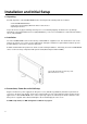
Installation and Initial Setup ■ Unpacking Carefully unpack the V-R171X-IMD-HDSDI monitor and verify that the following items are included: • V-R171X-IMD-HDSDI Monitor • V-PS12-5V-1 Power Supply with 2-Pin Twist Lock Connector • Operating Instructions Inspect the unit for any physical damage that may have occurred during shipping. Should there be any damage, immediately contact Marshall Electronics at (800) 800-6608. If you are not located within the continental United States, call +1 (310) 333-0606.
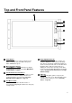
Top and Front Panel Features Power Button Turn the monitor off or on by pressing the power button. In the ON state, the LED on the power button will illuminate green. Menu Navigation Buttons Use the Menu, ↑, ↓, and Select buttons to display and navigate the on-screen menu (See Main Menu and Navigation – Page 8). User-Definable Function Buttons Two user-definable function buttons can be used for direct access to various settings.
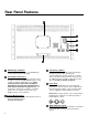
Rear Panel Features HD-SDI Input and Output The V-R171X-IMD-HDSDI has one HD-SDI input and one active loop-through output. RS-422/485 Serial Interface The RS-422/485 ports are used to remotely control the IMD or all V-R171X-IMD-HDSDI features, using a variety of industry standard protocols. (Note: Connector/pin-out may need to be adapted depending on protocol and controlling device used. See pin-out details on page 26.) Only one connection to either port is needed to control the monitor.
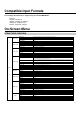
Compatible Input Formats The following SDI standards are supported by the V-R171X-IMD-HDSDI: 525i, 625i 1035i/60, 1035i/59.94 1080i/60, 1080i/59.94, 1080i/50 1080psF/24, 1080psF/23.98 720p/60, 720p/59.94, 720p/50 On-Screen Menu STRUCTURE OVERVIEW Marker Setup Video Config Color Config System Config Main Deinterlacer OSD Config IMD Config Service Marker 16:9 Off, 95%, 93%, 90%, 88%, 80%, 1.85:1, 2.
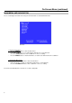
On-Screen Menu (continued) MAIN MENU AND NAVIGATION Access and navigate the main menu using the 4 menu buttons or the RotoMenu™ knob: Main Menu Using the menu buttons • Press the MENU button to enter the main menu. • Use the ↑ and ↓ buttons to scroll through the main menu or each submenu. • Press the SELECT button to enter a submenu or choose a setting. • Press the MENU button to exit the main menu, or return to the main menu from a submenu.
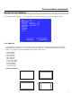
On-Screen Menu (continued) MARKER SETUP SUBMENU Use the Marker Setup submenu to select various types of markers and settings in 4:3, 16:9, or Full Screen mode. Marker Setup Submenu ■ 16:9 Markers Use this setting to superimpose one of 10 markers on the screen when in 16:9 or Full Screen mode. This setting is disabled when the aspect ratio is set to 4:3, or when Pixel-to-Pixel mode is enabled. Note that in Full Screen mode, markers are vertically stretched along with the picture to fit the 16:10 screen.
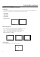
On-Screen Menu (continued) MARKER SETUP SUBMENU (continued) ■ 4:3 Markers Use this setting to superimpose one of 5 markers on the screen when in 4:3 mode. This setting is disabled when the aspect ratio is set to 16:9 or Full Screen, and when Pixel-to-Pixel mode is enabled.
On-Screen Menu (continued) VIDEO CONFIGURATION SUBMENU Use the Video Configuration submenu to select various video settings such as monochrome mode or blue-only mode. Video Configuration Submenu ■ Monochrome Mode Use this setting to enable monochrome mode. Only the luminance of the image will be displayed as a grayscale picture. ■ Blue-Only Mode Use this setting to enable Blue-Only mode. This mode displays only the blue color component of the image, switching off the red and green components.
On-Screen Menu (continued) VIDEO CONFIGURATION SUBMENU (continued) ■ Pixel-to-Pixel Mode Use this setting to enable Pixel-to-Pixel mode.
On-Screen Menu (continued) VIDEO CONFIGURATION SUBMENU (continued) ■ Aspect Ratio Settings (continued) 00:00:00:00 00:00:00:00 00:00:00:00 IMD Text IMD Text Scaled 4:3 4:3 00:00:00:00 00:00:00:00 IMD Text 16:9 IMD Text Full Screen (16:10) ■ Curtain Color Use this setting to choose the default color displayed on the screen when no video input is present. Available colors are blue, red, green, white, and black.
On-Screen Menu (continued) COLOR CONFIGURATION SUBMENU Use the Color Configuration submenu to adjust the color temperature of the display. Color Configuration Submenu ■ Ctemp/Gamma Use this setting to choose one of three color temperature / gamma presets: • • • • D55 (5500K) D65 (6500K) D93 (9300K) Linear (No gamma applied) ■ Red, Green, and Blue Offset Use the offset controls for red, green, and blue to adjust the color temperature of the display.
On-Screen Menu (continued) SYSTEM CONFIGURATION SUBMENU Use the System Configuration submenu to control various system parameters. System Configuration Submenu ■ Gray Levels Use the Gray Levels menu option to view 256 levels of flat field gray. This feature is useful for color temperature comparison and calibration. The input must be disconnected for the Gray Levels feature to function.
On-Screen Menu (continued) SYSTEM CONFIGURATION SUBMENU (continued) ■ Saving and Loading User Presets Use the SAVE CONFIG and LOAD CONFIG menus to save current settings to one of 6 presets, or load a preset. Each Preset saves all monitor settings except for IMD configuration. • Use the LOAD CONFIG menu to load one of presets USR1 – USR6. Factory default settings can also be loaded by selecting MFG. (Factory defaults cannot be overwritten.
On-Screen Menu (continued) DEINTERLACER SUBMENU Use the Deinterlacer submenu to control the type of deinterlacing performed on interlaced input signals. System Configuration Submenu ■ Deinterlacer Mode User the Deinterlacer Mode option to set the type of deinterlacing algorithm used: • In Auto mode, the deinterlacer defaults to Motion Adaptive mode (see below), but uses Film Mode (see below) whenever a film cadence is detected.
On-Screen Menu (continued) DEINTERLACER SUBMENU (continued) ■ Film Mode Film mode uses specialized algorithms to correctly deinterlace content that originated in either 24fps or 25fps. Film Mode is automatically entered whenever a film-to-video cadence is detected in the content. Film cadence detection is active whenever the Deinterlacer Mode is set to Auto. Use the Film Mode setting to limit the film mode detection to a specific cadence.
On-Screen Menu (continued) OSD CONFIGURATION SUBMENU Use the OSD Configuration submenu to select a variety of information to be displayed on the screen. OSD Configuration Submenu ■ IMD State Use this setting to turn the IMD text display on or off. This setting affects both fixed string IMD text and remote IMD text commands (see IMD Configuration Submenu for details – page 22). ■ Status Display Use this setting to enable or disable status display.
On-Screen Menu (continued) OSD CONFIGURATION SUBMENU (continued) ■ OSD Tally Use this setting to choose how tally is displayed on the screen. The available OSD Tally options depend on the Tally Source selected in the IMD Configuration submenu (see page 22).
On-Screen Menu (continued) OSD CONFIGURATION SUBMENU (continued) ■ LED Tally Use this setting to enable or disable the LED Tally. When enabled, the yellow, red and green LEDs above the display will respond to tally commands, according to the Tally Source setting (see page 23). ■ Time Code Use this setting to enable time code display on the screen. Time code is de-embedded from the vertical ancillary data (VANC) within the SDI signal.
On-Screen Menu (continued) IMD CONFIGURATION SUBMENU ■ Overview The V-R171X-IMD-HDSDI features an In-Monitor Display (IMD) with the ability to display on-screen text and tally in three colors. IMD text, color, and alignment can be assigned to each screen locally using menu options (see below). Alternately, IMD text and tally can be remotely controlled via the RS-422/485 serial interface using several industrystandard protocols, including TSL v4.0 and Image Video.
On-Screen Menu (continued) IMD CONFIGURATION SUBMENU (continued) ■ IMD ID # The IMD ID # identifies each screen to the controlling device. When using the TSL protocol, the ID # of each screen should be manually set in conjunction with the controlling device. When using the Image Video protocol, the ID # may be set automatically by the controlling device, after each IMD is initially identified by IMD Name (see “IMD Name[S/N]” below). Available ID #s are 000-255.
On-Screen Menu (continued) IMD CONFIGURATION SUBMENU (continued) ■ Tally Source The V-R171X-IMD-HDSDI tally (OSD and LED) can be controlled in a variety of different ways. Use the Tally Source setting to choose how tally is controlled: Standard Use the Standard setting to control tally via contact closure on the HD-15 tally interface. Image Video HW Use the Image Video HW setting to control Image Video tally states via contact closure on the HD-15 tally interface.
On-Screen Menu (continued) SERVICE SUBMENU ■ Overview The Service submenu displays the status of the serial interface, for troubleshooting or debugging purposes only. Contact Marshall Electronics for further information.
Specifications ■ RS-422/485 SERIAL INTERFACE (RJ12) ■ PANEL Screen Size Display Area (h x v) Aspect Ratio Pixels Viewing Angle (h x v) Brightness Contrast Ratio Dot Pitch (h x v) Pixel Pitch (h x v) 17” Diagonal 367.20 x 229.50 mm 16:10 Native (4:3/16:9 Modes) 1920 x RGB x 1200 140° x 120° 2 400 cd/m 600:1 0.064 x 0.191 mm 0.191 x 0.191 mm Protocols: Image Video, TSL v4.0, MEI Pin No.
Specifications (continued) Maintenance ■ Screen Cleaning Periodically clean the screen surface using ammonia-free cleaning wipes (Marshall Part No. V-HWP-K). A clean microfiber cloth can also be used using only non-abrasive and ammonia-free cleaning agents. Do not use paper towels. Paper towel fibers are coarse and may scratch the surface of the polycarbonate faceplate or leave streaks on the surface. Antistatic and fingerprint resistant cleaning agents are recommended.
Marshall Electronics, Inc. 1910 East Maple Ave. El Segundo, CA 90245 Tel: (800) 800-6608 / (310) 333-0606 • Fax: 310-333-0688 www.LCDRacks.com • sales@lcdracks.