Marshall Electronics Model No.
Table of Contents Product Overview .........................................................................................................................3 Features....................................................................................................................................3 Installation and Accessories .........................................................................................................4 Monitor Front ..............................................................
Product Overview The Quad Viewer Series is the latest addition to Marshall's line of IMD-equipped monitors. The monitor features a full resolution 1920 x 1200 LCD panel, built-in high quality HD Quad Splitter, four independent HDSDI inputs, one DVI-I input, IMD (In-Monitor Display) capability, Audio Presence indicator, and Time Code. Video and DVI-I both offer full screen mode, while quad-split mode is scaled to fit onscreen in the highest resolution.
Installation and Accessories Unpacking Carefully unpack the QV171X-HDSDI monitor and verify that the following items are included: • QV171X-HDSDI Monitor • V-PS12V-1 Power Supply with 2-Pin Twist Lock Connector • Operating Instructions Accessories The QV171X-HDSDI supports VESA standard 75mm devices. Marshall Electronics offers a VESA stand with Pivot capabilities (VP-LCD171H-ST-01).
Monitor Front (POWER) Button (Ch. 1 – Ch. 4) Channel Select (Quad) Layout DVI-I (F1-F2) Function Buttons RotoMenu (BRIGHT – COLOR – CONTRAST) Image Adjustment Buttons [Power] [F1 , F2] Turn the monitor off or on by pressing the power button. The LED on the power button is at full illumination when the monitor is OFF. Two user-definable function buttons can be used for direct access to various settings. Functions are assigned using the on-screen menu. [Ch.
Monitor Rear RS-422 / 485 VESA Mount Service Connector Tally DVI-I Input Connector Power Input HD/SDI Input + Output Connectors VESA Mount VESA standard 75 mm hole pattern is provided to accommodate a variety of custom mounting options. RS-422 / 485 Serial Interface The RS-422/485 ports are used to remotely control the IMD or all QV171X-HDSDI features using a variety of industry standard protocols. Only one connection to either port is needed to control the monitor.
Compatible Input Formats The following SDI standards are supported by the QV171X-HDSDI: 525i, 625i 1035i/60, 1035i/59.94 1080i/60, 1080i/59.94, 1080i/50 1080psF/24, 1080psF/23.98 1080p23.98, 1080p/24, 1080p/25, 1080p/29.97, 1080p/30 720p/60, 720p/59.94, 720p/50 720p/25, 720p/29.
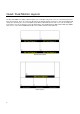
Quad / Dual Monitor Layouts The QV171X-HDSDI can display 4 different input sources simultaneously. Each source is scaled and positioned to fit the desired layout. There are a total of 4 different layouts illustrated below. Each press of the [Layout] Button will change the current layout to the next available layout. When in Quad Mode, Ch.4 video source can be changed to be the DVI-I source at any time by pressing the DVI-I Button. This will illuminate the DVI-I Button LED.
Quad Layout 3 Layout 4 9
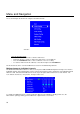
Menu and Navigation Access and navigate the main menu using the RotoMenu™ knob: Main Menu Using the RotoMenu knob • Press the RotoMenu™ knob to enter the main menu. • Rotate the knob to scroll up or down in the main menu or each submenu. • Press the RotoMenu™ knob to enter a submenu or choose a setting. • To return to main menu from submenu, select ‘Back’ and press the RotoMenu™. The menu timeout can be set in the OSD Timeout section of the OSD Config submenu.
Your current position in the menu is indicated by the green highlight. When you have highlighted the particular channel you would like to modify, press the RotoMenu knob. The box you have selected will change, indicating that this channel is now your choice to be modified, as shown below: To apply a change to the particular channel, turn your RotoMenu left or right after you have selected a channel (the channel is highlighted in red).
To turn the Group Link option on from the above state, simply press the RotoMenu knob. The Group Link Icon will change from a broken Group Link icon to a completed Group Link icon, as shown below: The completed Group Link icon indicates that any change that you make to an individual channel, as shown section before this, will be applied to all other channels. To turn this off, simply highlight the Group Link icon again and press the RotoMenu knob.
2. Display SMPTE split-field color bars on the monitor using an external source. 3. Enable Monochrome mode. 4. Locate the pluge pattern (super black, black, and gray bars) at the lower-right corner of the screen. Adjust the Brightness knob until there is no visible difference between the super black and black bars, but the gray bar is still visible. 5. Adjust the Contrast knob until an even grayscale appears along the top bars. 6. Disable Monochrome mode. 7.
■ Curtain Color Use this setting to choose the default color displayed on the screen when no video input is present. Available colors are blue, red, green, white, and black. ■ Ctemp/Gamma Use this setting to choose one of three color temperatures / gamma presets or to remove gamma application: • • • • Linear (No gamma applied) 55K 65K 93K ■ Framelock Preference Used to designate the Primary Channel as a reference for synchronizing image scaling when in any Quad Mode.
■ DVI Select Use this to select the DVI-I input as the Ch. 4 video input by setting this to On. Setting this to Off makes HDSDI Input 4 the video source for Ch. 4. ■ Analog Phase (DVI-Analog or VGA input only) Adjusts the analog phase value to improve picture quality on DVI-A or VGA Sources. This adjusts the signal phase (not color phase) of the analog-to-digital conversion.
Each column adjusts a particular input channel, from HD/SDI Ch1-Ch4 to the DVI-I input. For the DVI-I input, you can adjust the Offset and Gain for either a DVI-D or DVI-A input. The Reset option allows you to return to the default settings for each individual channel. System Configuration Submenu System Configuration Submenu ■ User-Definable Function Buttons Use the Function 1 and Function 2 menu items to define each function button on the front panel of the monitor.
• Use the LOAD CONFIG menu to load one of presets USR1 – USR6. Factory default settings can also be loaded by selecting MFG. (Factory defaults cannot be overwritten.) • Use the SAVE CONFIG menu to save the current settings to a preset from USR1- USR6. Full System Restore Use To perform a full system restore, which resets ALL adjustable fields on the monitor to their “fresh-fromfactory” state, press the Power, F1 and F2 button simultaneously.
Status Display ■ OSD Tally Use this setting to choose how tally is displayed on the screen. The available OSD Tally options depend on the Tally Source selected in the IMD Configuration submenu (see page 22). When the Tally Source is set to Standard (contact closure), OSD Tally can be set to Off, RGY, RG, or GR: • Off • RGY On-screen tally is disabled Red, yellow, or green tally signals are indicated at both the bottom left and bottom right corners of the screen.
■ Audio Monitor Use the Audio Monitor menu option to enable or disable the audio presence indicator icon. When enabled, this icon indicates whether embedded audio is present in the HD/SDI video input. A red circle and cross will flash on the icon if no embedded audio is present. Embedded Audio Present No Embedded Audio ■ CC Monitor (Closed Captioning) Use the CC Monitor menu option to enable or disable the Closed Captioning presence indicator icon.
IMD Configuration Submenu The QV171X-HDSDI features an In-Monitor Display (IMD) with the ability to display on-screen text and tally in three colors. IMD text, color, and alignment can be assigned to each screen locally using menu options (see below). Alternately, IMD text and tally can be remotely controlled via the RS-422/485 serial interface using several industry-standard protocols, including TSL v4.0 and Image Video.
TSL v4.0 Use the TSL v4.0 protocol setting when controlling the IMD from a TSL tally controller, or other controlling device which utilizes the TSL v4.0 protocol. The IMD # must be set for each screen in conjunction with the controlling device. MEI Use the MEI protocol setting when controlling the QV171X-HDSDI using the Marshall Network Controller box.
■ IMD Name (S/N) Use this setting to assign a name to each screen when using the Image Video or Marshall-IV protocols. The IMD name is equivalent to the Image Video serial number and is used by the Image Video controlling device to identify each screen. The default IMD Name(S/N) is “M00000.” It is recommended to maintain this naming scheme in order to avoid serial number conflicts with other Image Video devices on the same serial bus. Each name can be up to 16 ASCII characters.
■ IMD Fixed String Use this setting to display static IMD text on the screen. This setting is used to enter IMD text locally, when a serial protocol is not used for remote control. The IMD Fixed String is saved after power cycle. The IMD Fixed String will be overridden by serial protocol commands. Press RotoMenu™ knob to edit the IMD Fixed String. Rotate the RotoMenu™ knob to move the cursor.
Specifications ■ PANEL Screen Size Display Area (h x v) Aspect Ratio Pixels Viewing Angle (h x v) Brightness Contrast Ratio Pixel Pitch (h x v) 17.0” Diagonal 367.20 x 229.50 mm 16:10 Native 1920 x RGB x 1200 140° x 120° 2 330 cd/m 500:1 0.191mmx 0.191mm Burn-In Warning The QV171X-HDSDI uses a high quality TFT LCD panel. However, if a static image is left on the screen for 48 hours, there may be a 10 to 20 minute recovery period for the panel.
Dimensions 25
Maintenance ■ Screen Cleaning Periodically clean the screen surface using ammonia-free cleaning wipes (Marshall Part No. V-HWP-K). A clean micro-fiber cloth can also be used using only non-abrasive and ammonia-free cleaning agents. Do not use paper towels. Paper towel fibers are coarse and may scratch the surface of the polycarbonate faceplate or leave streaks on the surface. Antistatic and fingerprint resistant cleaning agents are recommended.
Marshall Electronics, Inc. 1910 East Maple Ave. El Segundo, CA 90245 Tel: (800) 800-6608 / (310) 333-0606 • Fax: 310-333-0688 www.LCDRacks.com • sales@lcdracks.