Marshall Electronics Model No. QVW-1708 17.
Table of Contents Installation and Accessories..................................................................................................................3 Monitor Front.........................................................................................................................................4 Monitor Rear .........................................................................................................................................4 Front Controls ...............................
Installation and Accessories Unpacking Carefully unpack the QVW-1708 monitor and verify that the following items are included: - QVW-1708 Monitor V-PS12V-5A-XLR Power Supply Operating Instructions Accessories The QVW-1708 supports VESA standard 75 mm hole pattern accessories. Additionally, a desktop stand is available for this product. Please contact Marshall Electronics for further information.
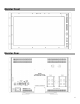
Monitor Front Monitor Rear 4
Front Controls POWER MENU / / / SEL Control Power going to the front panel. As an alternative to the ROTOMENU™, these buttons provide the ability to navigate through the menu with the MENU / / / SEL buttons. A – B (Input buttons) Press the A or B to select which module input to display on the screen. Each press of an input button cycles between the available inputs on that module. MUTE Press the MUTE button to mute the output to the headphone jack.
Rear Inputs LINE OUT The Line Out, 1/8”, jack on the back of the monitor takes two channels of embedded SDI audio and provides a Line Level Output. The volume is constant and can not be adjusted via the VOLUME or MUTE functions on the monitor. Headphone Jack The Headphone, 1/8”, jack on the front panel takes two channels of embedded SDI audio for your listening pleasure. The Headphone jack provides audio with adjustable levels via the ROTOMENU knob.
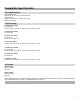
Compatible Input Formats SDI / HDSDI Formats 567i 50, 625i 59.94 720p 23.98, 24, 25, 29.97, 30, 50, 59.94, 60 1035i 59.94, 60 1080p 23.98, 23.98sF, 24, 24sF, 25, 29, 30 1080i 50, 59.94, 60 3G SDI Formats Level A 1920 x 1080 p 50, 59.94, 60p 23.98, 23.98sF, 24, 24sF, 25, 25sF, 29.97, 29.97sF, 30, 30sF Level A 1920 x 1080 i 50, 59.94, 60i Level A 1280 x 720 p 50, 59.94, 60 23.98, 24, 25, 29.97, 30 Level A 2k x 1080 p 23.98, 23.98sF, 24, 24sF, 25, 25sF, 29.97, 29.97sF, 30, 30sF Level B 1920 x 1080 p 50, 59.
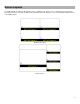
Screen Layouts The QVW-1708-Q can display 4 different input sources simultaneously. Each source is scaled and positioned to fit the desired layout. There are a total of 4 different layouts illustrated below. Each press of the Layout Button will switch to the next available layout.
Quad Layout 3 Layout 4 9
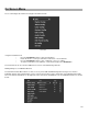
On Screen Menu Access and navigate the main menu using the RotoMenu™ knob: Main Menu Using the RotoMenu knob • Press the RotoMenu™ knob to enter the main menu. • Rotate the knob to scroll up or down in the main menu or each submenu. • Press the RotoMenu™ knob to enter a submenu or choose a setting. • To return to main menu from submenu, select ‘Back’ and press the RotoMenu™. The menu timeout can be set in the OSD Timeout section of the OSD Config submenu.
To modify a channel, enter a specific submenu (Marker Setup) and a specific function in that submenu (Marker Enable) by highlighting it with the RotoMenu and pressing the knob to confirm your selection. Your current position in the menu is indicated by the white highlighted box. When you have selected the desired function, you are given the option of modifying one channel or All channels. Using the RotoMenu, you can select which channel you would like to modify.
■ Marker Enable Enable or disable on screen markers for each individual channel. ■ Marker 16:9, Marker 4:3 The Marker 16:9 and Marker 4:3 functions allow you to adjust the screen markers for the 16:9 and 4:3 Aspect Ratios, respectively. ■ Marker Backgrd Use this function to set the opacity of the area outside of the on screen markers. You can choose between Off, 50% and Black. ■ Center Marker Enable or disable the Center Marker cross hairs for each individual channel.
1. Allow the monitor to warm up for at least 5-10 minutes. 2. Display SMPTE split-field color bars on the monitor using an external source. 3. Enable Monochrome mode. 4. Locate the pluge pattern (super black, black, and gray bars) at the lower-right corner of the screen. Adjust the Brightness knob until there is no visible difference between the super black and black bars, but the gray bar is still visible. 5. Adjust the Contrast knob until an even grayscale appears along the top bars. 6.
■ 4K Mode Use this setting to enable the 4K Mode, which synchronizes all four inputs to allow the monitor to display a 4K signal. When in 4K mode, all functions in the menu will be available, and controls for COLOR, BRIGHTNESS and CONTRAST will work on all four quadrants simultaneously.
Color Configuration Submenu Use the Color Configuration submenu to adjust the Red, Green and Blue Offset and Gain values of all four input channels. ■ Red, Green, and Blue Offset Use the offset controls for red, green, and blue to adjust the color temperature of the display. Each setting adjusts the offset, or brightness, of each individual color component. These settings will affect whichever color temperature preset is selected.
System Configuration Submenu Use the System Configuration submenu to control various system parameters such as GPI, function button settings and User definable presets. System Configuration Submenu ■ Green, Red and Yellow GPI Use the Green, Red and Yellow GPI menu items to set a certain action when the Green, Red or Yellow tally connector is activated through dry contact on the tally connector on the back of the unit. The following options are available for each input: .
■ User-Definable Function Buttons Use the Function 1 – Function 4 menu items to define each function button on the front panel of the monitor. The following options are available for each button: •Marker •Center Marker •Marker Enable •Marker Backgrd •IMD •Anc. Time Code •OSD Tally •Anc.
OSD Configuration Submenu Use the OSD Configuration submenu to select a variety of information to be displayed on the screen. OSD Configuration Submenu ■ IMD State Use this setting to enable or disable the IMD text display. This setting affects both the fixed string (entered through display menus) and remote IMD text commands. ■ Status Display Use this setting to enable or disable status display. When enabled, the current video input standard is displayed on the top left of the screen.
■ OSD Tally Use this setting to choose how tally is displayed on the screen. The available OSD Tally options depend on the Tally Source selected in the IMD Configuration submenu. When the Tally Source is set to Standard (contact closure), OSD Tally can be set to Off, RGY, RG, or GR: • Off On-screen tally is disabled • RGY Red, yellow, or green tally signals are indicated at both the bottom left and bottom right corners of the screen.
■ Anc. Monitor Use the Ancillary Monitor menu option to enable or disable on screen audio, closed caption and timecode presence indicators. When enabled, Audio, CC608, CC708, LTC and VITC indicators are shown on the screen. A green circle will appear next to each data type if it is present in the SDI stream. Ancillary Monitor with input signal with no ancillary data ■ Ancillary Monitor with input signal with Audio, 608 CC and LTC timecode.
Audio Config Submenu Use the Audio Configuration submenu to configure Audio channel selection for the headphone jack, audio level and on screen audio display. Audio Configuration Submenu ■ Audio Bars This monitor provides audio level indicators for SDI streams with embedded audio. Support for up to 16 channels (labeled as Groups 1, 2, 3 and 4) is provided.
■ Left Ch. Select Use this setting to select which of the 16 possible channels you would like to monitor on the Left side of the stereo output. ■ Right Ch. Select Use this setting to select which of the 16 possible channels you would like to monitor on the Right side of the stereo output. ■ Mute The Mute function disables audio output from Headphone output on the monitor. This will NOT control the Line Out level of the monitor, only the Headphone output.
■ IMD ID # The IMD ID # identifies each screen to the controlling device. When using the TSL protocol, the ID # of each screen should be manually set in conjunction with the controlling device. When using the Image Video protocol, the ID # may be set automatically by the controlling device, after each IMD is initially identified by IMD Name. Available ID #s are 000-254. ■ IMD Group # Each screen can be assigned an IMD Group # when using the Marshall protocol. Available Group #s are 01-254.
Use the TSL/MEI 422 setting to control OSD tally via the TSL or Marshall serial protocols. ■ IMD Baud Rate Use this setting to choose the baud rate. The baud rate must be set in conjunction with the controlling device. Available baud rates are 300, 600, 1200, 2400, 4800, 9600, 19200, 38400, 57600, 115200. The TSL v4.0 protocol is fixed at 38400 bauds for correct functionality, but this can be changed on the monitor for custom purposes.
■ IMD Color Use this setting to choose the color of the IMD Fixed String text (see below). Available colors are red, green, and yellow. This setting does not affect text color when using IMD text via the Image Video or TSL v4.0 protocols (text color is set via the protocols). ■ IMD Alignment Use this setting to choose the horizontal alignment of the IMD text. IMD text can be justified on the left, center or right of the screen.
■ Netmask Use this field to set the appropriate Netmask compatible with your network. If you enable DHCP, this will be automatically set for you based on your current Network settings. ■ Gateway Use this field to set the appropriate Gateway compatible with your network. If you enable DHCP, this will be automatically set for you based on your current Network settings. ■ MAC Address The MAC address is an internal fixed address for each individual monitor.
Monitor Specifications Panel Specifications Screen Size Screen Resolution Brightness Contrast Ratio 17.3” 1920 x 1080 2 400 cd/m 600:1 Burn-In Warning The QVW-1708-Q uses a high quality LCD panel. However, if a static image is left on the screen for 48 hours, there may be a 10 to 20 minute recovery period for the panel. During recovery, a very faint image may be retained on the display. Put up a white image for 30 minutes to eliminate the retained image.
Dimensions 28
Warranty Marshall Electronics warranties to the first consumer that this QVW-1708 LCD monitor will, under normal use, be free from defects in workmanship and materials, when received in its original container, for a period of one year from the purchase date. This warranty is extended to the first consumer only, and proof of purchase is necessary to honor the warranty.