Marshall Electronics Model No. V-LCD70XHB-HDA Model No.V-LCD70XHB-HDMIPT Model No.V-LCD70XHB-3GSDI 7” Portable Field / Camera-Top Monitor Operating Instructions Marshall Electronics, Inc. 1910 East Maple Ave. El Segundo, CA 90245 Tel: (800) 800-6608 / (310) 333-0606 • Fax: 310-333-0688 www.LCDRacks.com • sales@lcdracks.
Maintenance ■ Screen Cleaning Periodically clean the screen surface using ammonia-free cleaning wipes (Marshall Part No. V-HWP-K). A clean microfiber cloth can also be used using only non-abrasive and ammonia-free cleaning agents. Do not use paper towels. Paper towel fibers are coarse and may scratch the surface of the polycarbonate faceplate or leave streaks on the surface. Antistatic and fingerprint resistant cleaning agents are recommended.
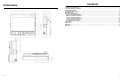
Dimensions Contents Installation and Initial Setup ................................................................................................................................................ 4 Front and Side Monitor Features......................................................................................................................................... 6 Rear Monitor Features ........................................................................................................................
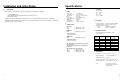
Installation and Initial Setup ■ Specifications Unpacking Carefully unpack the V-LCD70XHB monitor and verify that the following items are included: Power Input 4-Pin Male XLR ■ PANEL Screen Size Display Area (h x v) Aspect Ratio Pixels Color Depth Viewing Angle (h x v) Brightness Contrast Ratio Pixel Pitch (h x v) • V-LCD70XHB Monitor • V-PS12-5V-XLR Power Supply with 4-Pin Female XLR Connector • Operating Instructions Inspect the unit for any physical damage that may have occurred during shipping.
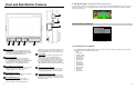
System Information Submenu System Information System Keypad Module (3GSDI) \ V3.xx vx.xx vx.xx System Information Submenu ■ System This shows the System firmware version of your monitor. ■ Keypad This shows the Keypad firmware version of your monitor. ■ Module This shows your module version (HDMIPT or 3GSDI) and the firmware version of your module.
Front and Side Monitor Features ■ SDI Signal Strength (V-LCD70XHB-3GSDI Model Only with 3GSDI-CLI module) Use this setting to enable an on screen indicator of your current SDI signal strength. Although this is not meant to be an absolute measurement of your SDI Signal Strength, this feature can be useful in determining the stability of the digital data along your cable run.
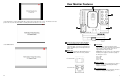
Rear Monitor Features Use the 16:9 option to scale the HDMI DSLR video output to fit the 16:9 portion of the screen. This will also remove the portion of the on screen video that is NOT recorded by the DSLR camera due to sensor crop. Use the Full Screen to Component and Composite Input and Output The V-LCD70XHB has HD component (YPbPr), composite as well as active loop-through outputs for each analog input. See page 8 for supported video formats. The BNC inputs are internally terminated with 75 ohms.
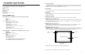
Compatible Input Formats The following standards are supported by the V-LCD70XHB monitors: Composite (CVBS) NTSC, PAL Component (YPbPr) 480i60, 576i50 720p (30, 29.97, 25) 720p ( 60 / 59.94 / 50) 1080p (30, 29.97, 25, 24, 24 sF, 23.98, 23.98 sF) 1080i (60 / 59.94 / 50) 3GSDI and HDMIPT Inputs V-LCD70XHB-3GSDI – V-LCD70XHB monitor with Triple-Rate SDI Input / Output SD-SDI – 480i 59.94, 576i 50 HD-SDI – 720p (60 / 59.94 / 50 / 30 / 29.97 / 25) 1080i (60 / 59.94 / 50) 1080p (30 / 29.97/ 25 / 24 / 24sF/ 23.
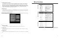
Menu Overview The Peaking Filter is used to aid the camera operator in obtaining the sharpest possible picture. When activated, all color will be removed from the display and a black-and-white image will remain. The internal processor will display RED color on the screen where sharp edges appear. When the camera operator adjusts (racks) the focus control (on the camera lens), different parts of the image will have RED colored edges. This indicates that the portion of the image is sharp – or in focus.
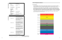
System Configuration Filter Configuration Submenu Input Format OSD On, Off, 5 sec Curtain Color Blue, Green, Black Splash Screen On, Off Contrast/Backlight Contrast, Backlight Freeze Input Image Flip Manufacturer Default HDMI Color Space HDMI Aspect Ratio HDMI DSLR Ratio Off, On Off, On Function Presets 5 SDI Signal Strength ■ False Colors The V-LCD70XHB has a false color filter to aid in the setting of camera exposure.
2. Use the BRIGHT, COLOR, TINT and CONTRAST knobs to move the LEFT, RIGHT, TOP and BOTTOM borders of the safe area to your desired position. When you have reached the desired location for the borders, press the MENU button. If you began the marker adjustment using one of the predefined safe areas and made an adjustment, the marker selection will automatically convert to the User marker setting.
and the luminance of your monitor. The lowest gamma level available, 1.6, will cause the image to appear brighter. The highest gamma level available, 2.4, will cause the image to appear darker. The chart below shows this on a scale. Gamma Correction ■ Full Screen Markers Use this setting to superimpose one of 7 markers on the screen when in Full Screen mode. This setting is disabled when the aspect ratio is set to 16:9 or 4:3, or when Pixel-to-Pixel, Underscan, or H/V Delay is enabled. 1 0.
■ Check Field Marker Configuration Submenu Use the check field modes for monitor calibration or to analyze individual color components of an image. In Monochrome mode, all color is disabled and only a grayscale image is shown. In Blue, Green, and Red check field modes, only the selected color will be shown.
This Pixel-to-Pixel mode bypasses the monitor’s internal scaling function and displays incoming images in their native resolution and aspect ratio, with a one-to-one mapping: • For incoming formats smaller than the native resolution of the LCD panel (800 x 480), the image will be displayed in the center of the screen using only the necessary LCD pixels. For example, NTSC images will occupy exactly 720 x 480 pixels. The surrounding pixels will be black.