OPERATIONS MANUAL & PARTS LIST MODEL: 1200MP Mortar-Plaster Mixer WS509 3-2012/Rev.A 104 S. 8th Ave. Marshalltown, IA Phone 800-888-0127 / 641-753-0127 Fax 800-477-6341 / 641-753-6341 www.marshalltown.
of 22
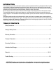
INTRODUCTION This owner’s manual provides the information needed to operate and maintain this Gilson by Marshalltown Mixer. Carefully read and follow all safety and operating instructions in this manual. Also, be sure every operator of this mixer reads this manual before operating the mixer. The replacement of any part on this mixer by other than the manufacturer’s authorized replacement part may adversely affect the performance, durability or safety of the product. Be sure safety precautions are observed.
SAFETY PRECAUTIONS This is the industry’s safety alert symbol. This symbol calls attention to items or operations that could be dangerous. This symbol can be found throughout this manual and on safety decals on the mixer. Read these messages carefully. THE FOLLOWING PRECAUTIONS ARE SUGGESTED TO HELP PREVENT ACCIDENTS. A CAREFUL OPERATOR IS THE BEST OPERATOR. MOST ACCIDENTS CAN BE AVOIDED BY OBSERVING CERTAIN PRECAUTIONS.
WARRANTY This mixer is warranted to the original purchaser only, to be free of defects in material and workmanship under normal use, for one year from purchase date. Marshalltown Company shall without charge, repair or replace parts which are found to be defective. All transportation charges for replacement parts must be bourne by the purchaser. For warranty service, the product must be delivered, with proof of purchase date, to the dealer of original purchase, or any factory authorized service dealer.
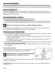
TOW POLE ASSEMBLY The tow pole assembly is located on the front of the mixer and is used for transport only. For transport, pull the tow pole assembly out, line up the holes and insert the L-shaped pin through holes. When operating the mixer, pull the L-shaped pin out of the hole and push tow pole assembly all the way in. Line up the holes and insert the L-shaped pin through the holes. MIXER TRANSPORT Secure drum by engaging drum lock. Secure all moveable parts, including the rear housing.
OPERATING THE MIXER STARTING THE MIXER To avoid personal injury, be sure control lever is in the neutral position before starting engine/motor Start the mixer engine/motor. Refer to the engine/motor manual for proper starting procedures. When the engine/motor is warmed up and is running smoothly, move the control lever to the neutral position. EXTENSION CORDS FOR ELECTRIC MOTORS The following size extension cords should be used: length of cord, up to 100 ft.
OPERATING GUIDELINES MASONRY CONSTRUCTION GUIDELINES The strength and durability of brick masonry depends upon the quality of the brick, the quality of the mortar and the workmanship in laying. The strength also depends upon adequate bond and the shape of the masonry unit. Brick quality – Characteristics are hardness and density. Brick for masonry which is exposed to weather or where strength is desired should have a crushing strength of not less than 2500 PSI.
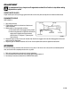
ADJUSTMENT To avoid personal injury, always turn off engine/motor and wait for all motion to stop before making adjustments or repairs RUBBER WIPER BLADES Adjust rubber wipers so they fit snugly against the drum but not to the point that they fold over when the blades rotate. ENGINE/MOTOR DRIVE SEE FIGURE 4. 1. Align pulleys correctly 2. Tighten locking collars in the direction of rotation and tighten setscrews. 3. Adjust tension on the engine belt as follows: A.
FIGURE 5: DRUM AND DRIVE 10 of 22
FIGURE 5: DRUM AND DRIVE REF # NAME 1 Bearing Hanger 2 Grease Fitting 3 Gear (Gasoline Powered Models) 3 Alt Gear (Electric Powered Models) 4 Drum Shell Assembly 5 Grill Assembly 6 Bearing Support Assembly 7 Drum Tilt Lever 8 Drum Seal 9 Seal Housing 10 Seal Retainer 11 Shaft Seal 12 Bearing, Drum Shaft (comes w/232463) 13 Drum Shaft 14 Locking Collar 15 Capscrew, Hex Hd 1/2-13 x 1 1/2 Gr.
FIGURE 6: MIXING BLADES 12 of 22
FIGURE 6: MIXING BLADES REF # NAME 1 Mixing Arm Assembly, Engine End 2 Mixing Arm Assembly, Tow End 3 Mixing Arm Cap 4 Drum Wrap Wiper 5 Wrap Wiper Backing Plate 6 End Wiper Backing Plate 7 Drum End Wiper 8 Capscrew, Hex HD 5/8-11 x 2 Gr 5 9 Capscrew, Hex HD 3/8-16 x 1 1/2 Gr 5 10 Nut, Hex 5/8-11 11 Nut, Hex 3/8-16 12 Washer, 5/8 Spring Lock 13 Washer, 3/8 Spring Lock 14 Side Arm Assembly, Tow End 15 Side Arm Assembly, Engine End 16 Capscrew, Hex HD 3/8-16 x 1 3/4 Gr 5 17 Washer, 3/8 Flat * Common hardware,
FIGURE 7: ENGINE HOUSING 14 of 22
FIGURE 7: ENGINE HOUSING REF # 1 2 3 4 5 6 7 8 9 10 11 12 13 14 15 16 17 18 19 NAME Engine Housing Assembly w/decals Housing Base Assembly Reflector T-Handle Latch Handle, Engine Housing Rivet, Handle Rubber Bumper Housing Base Front Plate Screw, Thread Forming 5/16-18 x 1/2 Screw, Sheet Metal #10-24 x 3/8 Axle Assembly Hub Assembly (includes:) Bearing Cup Bearing Cone Hub Cap Lug Nut Seal Spring, Suspension Wheel and Tire Assembly Wheel Tire, A78-13 Valve Stem w/cap 20 Capscrew, Hex Hd 1/2-13 x 1 1/2 Gr 5
FIGURE 8: FRAME, DRIVE & CLUTCH CONTROL 16 of 22
FIGURE 8: FRAME, DRIVE & CLUTCH CONTROL REF # NAME 1 Frame, Engine and Drive Support 2 Frame Assembly 3 Pin and Chain Assembly 4 Pin, Cotter 3/16 x 1 5 Spring Clip 6 Tow Pole Assembly Pintle (std) 7 Capscrew, Hex Hd 1/2-13 x 3 1/4 Gr 5 8 Handle, Drum Lock 9 Grip Handle 1/2” (Upper) 9 Grip Handle 5/8” (Lower) 10 Capscrew, Hex Hd 1/2-13 x 1 1/2 Gr 5 11 Nut, 1/2-13 Jam 12 Setscrew, Sq Hd 1/2-13 x 3 13 Washer, 1/2 Flat 14 Shaft, Pinion (Gasoline Models) 14 Shaft, Pinion (Electric Models) 15 Gear, Pinion (Gasoli
FIGURE 9 ENGINE MOUNT 18 of 22
FIGURE 9 ENGINE MOUNT REF # 1 2 3 4 5 6 7 8 9 10 11 12 13 NAME PART# QUANTITY Frame, Engine and Drive Support MIX232412 1 Frame Assembly MIX245339 1 Pin and Chain Assembly *MIX70631 1 Pin, Cotter 3/16 x 1 *MIX70687 1 Spring Clip MIX232548 1 Tow Pole Assembly Pintle (std) *MIX70258 1 Capscrew, Hex Hd 1/2-13 x 3 1/4 Gr 5 *MIX70553 1 Handle, Drum Lock *MIX70649 1 Grip Handle *MIX23156 2 Capscrew, Hex Hd 1/2-13 x 1 1/2 Gr 5 *MIX71404 1 Nut, 1/2-13 Jam *MIX70803 1 Setscrew, Sq Hd 1/2-13 x 3 *MIX70498 1 Washer,
TROUBLE SHOOTING GUIDE FOR MP MIXERS ENGINE WON’T START: 1. Check for sufficient fuel. 2. Check oil level (some engines have an oil alert, preventing the engine from starting when oil level is low) 3. Was engine choked when starting? 4. Is engine flooded? 5. Check spark plug. (Clean and check gap). 6. If engine still won’t start, take to service center. BELT DRIVEN MODELS: 1. Check condition of belts, replace if necessary. 2. Check for oil or grease on belts as well as for loose belts. 3.
of 22
104 S. 8th Ave. Marshalltown, IA Phone 800-888-0127 / 641-753-0127 Fax 800-477-6341 / 641-753-6341 www.marshalltown.