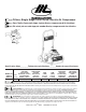
Oilless, Single Stage, Direct Drive, Electric Air Compressor Sans l’huile, d’une seule étape, à prise directe, compresseur d’air électrique Sin aciete, de una sola etapa, de mando directo, compresore de aire eléctrico Specification Chart________Tableau des spécifications_______Cuadro de especificaciones TANK CAPACITY GALLONS VOLTAGE/ AMPS/PHASE (TENSION/ AMPS/PHASE) (VOLTAJE/ AMP/FASE) CFM CFM (L/MIN) @ 40 PSI (2,8 BAR) 115/15/1 8.3 (235) (MODÈLE) (MODELO) H.P.
TABLE OF CONTENTS SAFETY GUIDELINES . . . . . . . . . . . . . . . . . . . . . . . . . . .3 OVERVIEW . . . . . . . . . . . . . . . . . . . . . . . . . . . . . . . . . . .6 Basic Air Compressor Components . . . . . . . . . . . . .6 COMPRESSOR CONTROLS . . . . . . . . . . . . . . . . . . . . . .7 ELECTRICAL POWER REQUIREMENTS . . . . . . . . . . . .9 Electrical Wiring . . . . . . . . . . . . . . . . . . . . . . . . . . . . .9 Extension Cords . . . . . . . . . . . . . . . . . . . . . . . . . . . .
SAFETY GUIDELINES The following information relates to protecting YOUR SAFETY and PREVENTING EQUIPMENT PROBLEMS. To help you recognize this information, we use the following symbols. Please read the manual and pay attention to these sections. DANGER: – A POTENTIAL HAZARD THAT WILL CAUSE SERIOUS INJURY OR LOSS OF LIFE. WARNING: – A POTENTIAL HAZARD THAT COULD CAUSE SERIOUS INJURY OR LOSS OF LIFE. CAUTION: – A POTENTIAL HAZARD THAT MAY CAUSE MODERATE INJURY OR DAMAGE TO EQUIPMENT. WARNING 1. 2.
CONSIGNES DE SÉCURITÉ Les informations suivantes concernent VOTRE SÉCURITÉ et LA PROTECTION DU MATÉRIEL CONTRE LES PANNES. Pour vous aider à identifier la nature de ces informations, nous utilisons les symboles suivants. Veuillez lire le manuel et prêter attention à ces sections. DANGER: – DANGER POTENTIEL POUVANT ENTRAÎNER DE GRAVES BLESSURES OU LA MORT. AVERTISSEMENT: – DANGER POUVANT CAUSER DES BLESSURES GRAVES VOIRE MORTELLES.
PAUTAS DE SEGURIDAD La información que sigue se refiere a la protección de SU SEGURIDAD y la PREVENCIÓN DE PROBLEMAS DEL EQUIPO. Como ayuda para reconocer esta información, usamos los siguientes símbolos. Lea por favor el manual y preste atención a estas secciones. PELIGRO: - UN POSIBLE RIESGO QUE CAUSARÁ LESIONES GRAVES O LA PÉRDIDA DE LA VIDA. ADVERTENCIA: - UN RIESGO POTENCIAL QUE PODRÍA PROVOCAR GRAVES LESIONES O MUERTE.
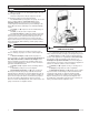
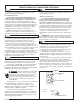
OVERVIEW \ VUE D’ENSEMBLE \ RESUMEN GENERAL BASIC AIR COMPRESSOR COMPONENTS Oilless air compressors are factory lubricated for life and do not require any oil. The basic components of the air compressor are the electric motor, pump, pressure switch, and tank. The electric motor (see A) powers the pump. The electric motor is equipped with an overload protector and an automatic reset. If the motor becomes overheated, the overload protector will shut it down to prevent damage to the motor.
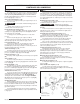
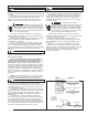
COMPRESSOR CONTROLS / COMMANDES DU COMPRESSEUR / CONTROLES DEL COMPRESOR COMPRESSOR CONTROLS ON/OFF Switch (see J) This switch turns on the compressor. It is operated manually, but when in the ON position, it allows the compressor to start up or shut down automatically, without warning, upon air demand. ALWAYS turn this switch to OFF when the compressor is not being used and before unplugging the compressor. Air Tool Pressure Regulator (see B).
COMMANDES DU COMPRESSEUR / CONTROLES DEL COMPRESOR Sortie de pistolet à trémie (voir H) Pour utiliser le pistolet à trémie. Pour assurer un débit maximal de volume d’air, ce raccord (H) de sortie comporte un dispositif d’arrêt automatique. La pression d’air est contrôlée par une soupape régulatrice de contróle (G) réglable qui prélève l’air supplémentaire au pistolet de texturation.
ELECTRICAL POWER REQUIREMENTS SPÉCIFICATIONS DE L'ALIMENTATION ÉLECTRIQUE ELECTRICAL WIRING Refer to the air compressor’s serial label for the unit’s voltage and amperage requirements. Use a dedicated circuit For best performance and reliable starting, the air compressor must be plugged into a dedicated circuit, as close as possible to the fusebox or circuit breaker. The compressor will use the full capacity of a typical 15 amp household circuit.
SPÉCIFICATIONS DE L'ALIMENTATION ÉLECTRIQUE __REQUERIMIENTOS DE ALIMENTACION ELECTRICA INSTRUCTIONS DE MISE À LA TERRE Ce produit doit être mis à la terre. En cas de court-circuit électrique, la mise à la terre réduit les risques de décharges électriques en fournissant un fil par lequel le courant électrique peut s'échapper. Ce produit est équipé d'un câble d'alimentation muni d'un fil de terre et d'une fiche de terre appropriée.
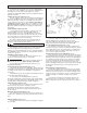
BREAK-IN OF THE PUMP \ RODAGE DE LA POMPE \ MARCHA DE LA BOMBA 1. 2. 3. 4. BREAK-IN OF THE PUMP Turn the pressure switch to the OFF position (see A). Open the petcock (see B). Turn in the counterclockwise direction. Plug in the power cord. Turn the pressure switch to the ON position (see C). The compressor will start. Allow the compressor to run for 30 minutes, to break in the internal parts.
OPERATING INSTRUCTIONS 1. 2. 3. DAILY STARTUP Turn the pressure switch to the OFF position (see A). Close the tank petcock (see D). Turn in the clockwise direction. Plug in the power cord. WARNING: High temperatures are generated by the electric motor and the pump. To prevent burns or other injuries, DO NOT touch the compressor while it is running. Allow it to cool before handling or servicing. Keep children away from the compressor at all times. 4. 4.
MODE D’EMPLOI MISE EN MARCHE QUOTIDIENNE 1. 2. 3. Placer le manocontacteur en position ARRÊT ( A). Fermez le robinet de purge du réservoir (D). Tourner vers la droite. Branchez le cordon d'alimentation. AVERTISSEMENT: La pompe et le moteur électrique produisent des températures élevées. Pour éviter les brûlures et autres blessures, NE touchez PAS le compresseur quand il est en marche. Laissez-le refroidir avant de le manipuler ou d'effectuer son entretien.
INSTRUCCIONES OPERATIVAS PRECAUCIÓN: El aire y la humedad que escapan del tanque pueden arrojar desechos que podrían causarle daño en los ojos. Al abrir la llave de descompresión use gafas de seguridad. ARRANQUE DIARIO 1. 2. 3. Coloque el conmutador activado por presión en la posición APAGADO (vea A). Cierre la llave de descompresión del tanque (vea D). Hágalo girar hacia la derecha. Enchufe el cordón eléctrico. AVERTENCIA: El motor eléctrico y la bomba producen altas temperaturas.
MAINTENANCE \ ENTRETIEN \ MANTENIMIENTO MAINTENANCE WARNING: To avoid personal injury, always shut off and unplug the compressor and relieve all air pressure from the system before performing any service on the air compressor. Regular maintenance will ensure trouble free operation. Your electric powered air compressor represents high quality engineering and construction; however, even high quality machinery requires periodic maintenance. The items listed below should be inspected on a regular basis.
MAINTENANCE \ ENTRETIEN \ MANTENIMIENTO CHECKING THE RELIEF VALVE Pull the relief valve daily to ensure that it is operating properly and to clear the valve of any possible obstructions. TESTING FOR LEAKS Check that all connections are tight. A small leak in any of the hoses, transfer tubes, or pipe connections will substantially reduce the performance of your air compressor. If you suspect a leak, spray a small amount of soapy water around the area of the suspected leak with a spray bottle.
SERVICE INTERVAL Perform the following maintenance at the intervals indicated below. Inspect and clean air filter . . . . . . . . . . . . . . . . . . . . . . . . . . . . . . . . . . . . . . . . . . . . . . .Daily Operate the pressure relief valves . . . . . . . . . . . . . . . . . . . . . . . . . . . . . . . . . . . . . . . .Daily Drain tank . . . . . . . . . . . . . . . . . . . . . . . . . . . . . . . . . . . . . . . . . . . . . . . . . . . . . . . . . . . .
TROUBLESHOOTING CHART Note: Troubleshooting problems may have similar causes and solutions. PROBLEM POSSIBLE CAUSE SOLUTION Low pressure or not enough air or Compressor does not stop Tank petcock is open Close petcock Fittings Leak Check fittings with soapy water. Tighten or reseal leaking fittings. DO NOT OVERTIGHTEN. Restricted air intake Clean or replace air filter element. Prolonged excessive use of air Decrease amount of air used.
TROUBLESHOOTING CHART Note: Troubleshooting problems may have similar causes and solutions. PROBLEM POSSIBLE CAUSE Pressure relief valve opens Tank pressure exceeded normal Contact authorized service center. operating pressure Motor will not run SOLUTION Pressure switch stuck Contact authorized service center. Tank pressure exceeds preset pressure switch limit Motor will start automatically when tank pressure drops below kick-in pressure of pressure tank.
DÉPANNAGE Remarque : Les problémes de dépannage peuvent avoir des causes et des solutions similaires. PROBLÉME CAUSE POSSIBLE SOLUTION Faible pression ou manque d'air ou compresseur fonctionnant sans arrêt Robinet de réservoir ouvert Fermer le robinet Fuite des raccords Vérifier les raccords à l'eau savonneuse. Resserrer ou étanchéifier les raccords. NE PAS TROP SERRER. Entrée d'air obstruée Nettoyer ou remplacer l'élément du filtre à air.
DÉPANNAGE Remarque : Les problémes de dépannage peuvent avoir des causes et des solutions similaires. PROBLÉME CAUSE POSSIBLE SOLUTION La soupape de sûreté s'ouvre La pression du réservoir dépasse la limite normale Contacter un centre d'entretien agréé. Manocontacteur bloqué Le moteur ne démarre pas La pression du réservoir dépasse la limite préréglée du manocontacteur Le moteur démarre automatiquement lorsque la pression du réservoir chute sous la pression d'enclenchement du manocontacteur.
CUADRO DE DETECCIÓN DE FALLOS Nota: Los problemas de detección de fallos pueden tener causas y soluciones similares. PROBLEMA CAUSA POSIBLE SOLUCION Presión baja o insuficiente cantidad de aire. o bien el compresor no se detiene El grifo de desagüe del tanque está abierto Cierre el grifo de desagüe Las conexiones tienen fugas Revise las conexiones con agua jabonosa. Apriete o vuelva a sellar las conexiones que tengan fugas. NO LAS APRIETE EN EXCESO.
CUADRO DE DETECCIÓN DE FALLOS Nota: Los problemas de detección de fallos pueden tener causas y soluciones similares. PROBLEMA CAUSA POSIBLE SOLUCION Sobrecalentamiento Ventilación deficiente Reubique el compresor en un área donde haya aire fresco, seco y con buena circulación. Superficies de enfriamiento sucias Limpie minuciosamente todas las superficies de enfriamiento de la bomba y del motor. Fugas en la válvula Comuníquese con un centro de servicio autorizado.
GLOSSARY OF TERMS CFM Cubic feet per minute; a unit of measure of air flow. PSI Pounds per square inch; a unit of measure of air pressure. Kick-in pressure Factory set low pressure point that starts the compressor to repressurize the tank to a higher pressure. Kick-out pressure Factory set high pressure point that stops the compressor from increasing the pressure in the tank above a certain level. Well-ventilated A means of providing fresh air in exchange for dangerous exhaust or vapors.
NOTES / REMARQUES / NOTAS 200-2360 25
PARTS DRAWING / DESSIN DES PIÈCES / ESQUEMA DE LA PIEZAS Torque to 15-20 lbs-in Torsión hasta 1,7 - 2,3 N m Note: Tighten compression nut handtight plus 1 full turn. Note: Serrez l'écrou de compactage solide plus 1 plein tour. Nota: Apriete la tuerca de la compresión handtight más 1vuelta completa.
PARTS LIST / LISTE DE PIÈCES / LISTA DE LAS PIEZAS Item Part No Art Art 1 2 3 4 5 6 7 Qty No / P Núm / P N/A 142-0122 N/A N/A 142-0118 142-0123 145-0399 Qté Cant 3 1 1 3 1 1 1 8 9 058-0007 040-0334 2 1 10 11 12 13 14 15 16 17 18 19 20 026-0233 059-0221 093-0019 150-0114 098-1105 092-0013 068-0052 059-0288 060-0115 059-0282 150-0116 1 3 3 1 1 2 4 2 2 4 1 20A 20B 20C 20D 20E 21 22 23 24 25 26 27 28 29 30 095-0016 033-0001 094-0026 061-0005 072-0001 098-2856 098-1062 098-1104 036-0051 036-0031 019-01
PARTS DRAWING / DESSIN DES PIÈCES / ESQUEMA DE LA PIEZAS Torque to 120-140 lbs-in Serrez de 120 à 140 lbs-in Torsión hasta 13,5 - 15,8 N•m Torque to 110-130 lbs-in Serrez de 110 à 130 lbs-in Torsión hasta 12,4 - 14,7 N•m Torque to 50-65 lbs-in Serrez de 50 à 65 lbs-in Torsión hasta 5,6 - 7,3 N•m Torque to 145-155 lbs-in Serrez de 145 à 155 lbs-in Torsión hasta 16,4 - 17,5 N•m 28 200-2360
PARTS LIST / LISTE DE PIÈCES / LISTA DE LAS PIEZAS Item Art Art 1 2 3 4 5 6 Part No No / P Núm / P 019-0186 019-0192 061-0186 042-0104 054-0226 043-0171 Qty Qté Cant 1 1 4 1 1 1 7 8 054-0225 N/A 1 1 9 160-0280 1 10 11 N/A 053-0096 1 1 12 13 14 --N/A 048-0105 1 1 1 15 16 17 18 19 20 21 22 23 N/A 027-0033 060-0144 061-0134 166-0088 166-0054 166-0120 166-0121 019-0199 1 1 1 1 1 1 1 1 1 Description Description Descripción Filter........................................Filtre....................
PARTS AND SERVICE Replacement parts and service are available from your nearest authorized Service Center. If the need arises, contact Customer Service as listed at right. When needing service, please contact the nearest authorized Service Center or call: When consulting with a Service Center or Customer Service, refer to the model number and serial number located on the serial label of the compressor. Proof of purchase is required for all transactions and a copy of your sales receipt may be requested.
PRODUCT WARRANTY ONE YEAR LIMITED WARRANTY Marshalltown Trowel Company (the Company) warrants, that for a period of twelve (12) months from the date of purchase, it will replace or repair, free of charge, for the original retail purchaser only, any part or parts, manufactured by the Company, found upon examination by the Company or its assigned representatives, to be defective in material or workmanship or both.
200-2360