BETAGAUGE 311A-Ex/321A-Ex Reference Manual
BETAGauge 311A-Ex/321A-Ex Reference Manual 1. Introduction . . . . . . . . . . . . . . . . . . . . . . . . . . . . . . . . . . . . . . . . . . . .1 1.1 Contacting Martel / Beta . . . . . . . . . . . . . . . . . . . . . . . . . . . . . . . . . . . .1 1.2 Standard Equipment . . . . . . . . . . . . . . . . . . . . . . . . . . . . . . . . . . . . . . .1 1.3 Safety Information . . . . . . . . . . . . . . . . . . . . . . . . . . . . . . . . . . . . . . . . .1 2. Calibrator Interface . . . . . . . . . . . . . . .
1. Introduction The BETA 311A-Ex/321A-Ex is designed to be a simple to use yet very versatile pressure calibrator. Its two internal pressure sensors combined with inputs for mA, switch contacts and an RTD probe allow the 311A-Ex/321A-Ex to calibrate virtually any pressure device. The BetaGauge 311A-Ex is a single sensor pressure calibrator; the BetaGauge 321A-Ex is a dual sensor pressure calibrator. The 311A-Ex uses the P1 port for all pressure inputs. The P2 port is only used on the model 321A-Ex.
Symbols Used The following table lists the International Electrical Symbols. Some or all of these symbols may be used on the instrument or in this manual. Symbol Description AC (Alternating Current) AC-DC Battery CE Complies with European Union Directives DC Double Insulated Electric Shock Fuse PE Ground Hot Surface (Burn Hazard) Read the User’s Manual (Important Information) Off On The following definitions apply to the terms “Warning” and “Caution”.
Warning To avoid possible electric shock or personal injury: • Do not apply more than the rated voltage. See specifications for supported ranges. • Follow all equipment safety procedures. • Never touch the probe to a voltage source when the test leads are plugged into the current terminals. • Do not use the calibrator if it is damaged. Before you use the calibrator, inspect the case. Look for cracks or missing plastic. Pay particular attention to the insulation surrounding the connectors.
2. Calibrator Interface Figure 1 shows the location of the process measurement inputs, while table 1 describes their use. Side View Figure 1 Pressure Measurement Inputs Table 1 Process Measurement Inputs 4 No. Name Description 1, 2 Input Terminals These terminal are used to measure current and a contact closure for switch test.
Figure 2 shows the location of the keys. Table 2 describes the function of each key. Figure 2 Keypad Table 2 Key Functions No.
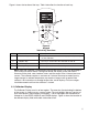
Figure 3 Display Table 3 Display Functions No. Name Description 1 Primary Parameters Indicates what is being measured. 2 Span Indicator Indicates the percent of the 4 to 20 mA span. (For mA functions only) 3 Pressure Units Indicates one of 17 pressure units available for display. 4 Units Indicates the unit of measure for the display. 2.1.1 Main Menu Functionality There are three options on the Main Menu, CONFIG, {current display} and MORE. The Main Menu is home for the menu display. 2.1.1.
P[2] ST = Switch Test with right side sensor. mA = Milliamps measure RTD = RTD Temperature Measurement (if a probe is connected). The following table shows which functions are available concurrently. An X in a column indicates that the mode in the current display will not be available for selection if the mode in that row is in use in any other active display.
Figure 4 Menu Map 8
9
2.2 Using the Backlight The backlight is controlled by the dedicated backlight key. It toggles on and off when the key is pressed; this is one of the few functions that cannot be controlled by the serial interface. There are no user configuration settings for the backlight. 2.3 Using the Zero Function When the ZERO KEY is pressed, the calibrator will zero the current display if a pressure mode is selected, and the pressure is within the zero limit.
function. The second and third options of a ‘sub-main’ menu are always the same. The NEXT option leads to the next ‘sub-main’ menu and the DONE option returns home . For the last ‘sub-main’ menu the NEXT option wraps around to home. See Figure 4 for a detailed mapping of the menu structure. A note on naming convention: If a ‘sub-main’ menu has subordinate menus, it will henceforth be referred to as {function} Main Menu. E.g. the display contrast sub-main menu will be called the Contrast Main Menu.
recall the set-up stored in the selected location. The display menu will automatically go home. 2.4.4 Setting AutoShut-off Parameters The calibrator can be set to automatically shut-off after a selected number of minutes; this function can also be disabled. To set the auto shut off parameters select the AUTO OFF option on the Auto Shut Off Main Menu. Use the arrow keys to select the number of minutes before the calibrator turns off or disable auto shut-off by scrolling all the way down.
2.4.6 Low resolution function. Due to the high accuracy of the 311A-Ex/321A-Ex the measured values are displayed with many digits, this might be an disadvantage in some cases, therefore the 311A-Ex/321AEx has a low resolution function. The function takes away the last digit. To turn the function on or off, proceed as follows: 1. With the calibrator turned on and operating press the F3 key to activate the MORE menu option. Press the NEXT button until RESOLUTION appears in the left text field.
3. Measuring Pressure To measure pressure, connect the calibrator using an appropriate fitting. Choose a pressure setting for the display being used. The calibrator is equipped with two internal sensors. Be sure to choose the sensor based on working pressures and accuracy. Warning Pressure sensors may be damaged and/or personnel injury may occur due to improper application of pressure.
3.1 Media Compatibility The calibrator utilizes a media isolated sensor to prevent sensor contamination. Whenever possible clean, dry air is the media of choice. If that is not always possible, make sure that the media is compatible with Nickel Plated Brass and 316 Stainless Steel. 4. Measuring Current Warning Check entity parameters before making any connections to this device. To measure current use the input terminals in the front of the calibrator. Select the mA function on one of the displays.
Figure 7 6. Performing a Pressure Switch Test Warning Check entity parameters before making any connections to this device.
To perform a switch test, follow these steps: 1. Change the setup to Setup 4 (default switch test). Setup 4: The upper display is set to [P1] ST, all other displays are off. Important NOTE: The pressure Switch Test can be performed with the following functions[P1] ST, [P2] ST. 2. Connect the calibrator to the switch using the pressure switch terminals. The polarity of the terminals does not matter. Then connect the pump to the calibrator and the pressure switch. 3. Make sure the vent on the pump is open.
8. Press the “NEXT” option to view when the switch closed, and the dead band. 9. Press the “NEW TEST” option to clear the data and perform another test. 10. Press the “DONE” option to end the test and return to the standard pressure setting. Example: [P1] ST will return to [P1]. Important NOTE: The previous example uses a normally closed switch. The basic procedure is still the same for a normally open switch, the display will just read “OPEN” instead of “CLOSE”. 7.
7.1 Using the mA Input Function The mA input function allows the user to read back the 4-20 mA output from the device being calibrated. This can be done passively – where the device under test directly generates 4-20 mA and can be read by the calibrator. 7.2 Calibrating a Pressure-to-Current Transmitter To calibrate a pressure-to-current transmitter (P/I), perform the following steps: 1. Connect the calibrator and the pump to the transmitter. 2. Apply pressure with the pump. 3.
7.3 Percent Error Function Warning Check entity parameters before making any connections to this device. The calibrator features a unique function which can calculate pressure vs. milliamp error as a percentage of the 4 to 20 mA loop span. The percent error mode uses all 3 screens and has a unique menu structure. It simultaneously displays pressure, mA and percent error. Figure 10.
4. Use SELECT to toggle through the UNIT options, and select NEXT to move on. 5. Use the ↑ and ↓ arrows to set the 100% point of the desired pressure range, select DONE SET when finished. 6. Again, use the arrows to set 0% point and select DONE SET when finished and the %ERROR mode will be ready to use.
Note: The 0% and 100% point will be saved in non-volatile memory until they are changed again by the user for the internal sensors, and external pressure modules. When using an external module the 0% and 100% are set to low and full scale of the module until the user changes it, or if it was previously saved. 8. Minimum and Maximum Storage Capability The 300 Series Pressure Calibrators have a min/max feature for capturing the minimum and maximum values of any displayed parameter.
9. Factory Setups The Calibrator is loaded with five factory setups. These setups are shown below. Setup 1: The upper display is set to [P1] mode and the middle is set to mA, lower is off. Setup 2: The upper display is set to [P2] mode and the middle is set to mA, lower is off. Setup 3: The upper display is set to [P1] mode and the middle is set to [P2], lower is off.
Setup 4: The lower display is set to [P1] switch test, the other displays are off. Setup 5: The upper display is set to [P1], the middle display is set to [P2] and the lower display is set to RTD. 10. Custody Transfer / Flow Calibration Warning Check entity parameters before making any connections to this device. The Model 311A-Ex/321A-Ex is ideal for flow computer calibration.
11. Specifications (18 °C to 28 °C unless otherwise noted.) General Instrument Setup Recall 5; last used on power-up Environmental Operating Temperature Storage Temperature -10 °C to +45 °C -20 °C to +60 °C Power Requirements Battery Battery Life 6.0 VDC Four (4) standard AA cells > 35 hours, typical usage Physical Dimensions Weight 8.3” H x 3.9” W x 1.8” D (21.082 x 9.906 x 4.572 cm) 1 lb. 4 oz. (0.567 kg) Product Compliance Markings Ex ia IIB T3 Gb (Ta=–10...
Accuracy Pressure 0.3 psi 1.0 psi 15 psi through 3000 psi 5 psi, 5000 psi, 10,000 psi ±0.1% F.S. ±0.05% F.S. ±0.025% F.S. ±0.035% F.S. mA ±0.015% of rdg ±0.002mA RTD (ohms) ±0.015% of rdg ±0.02 ohms; or ±0.1°C @ 0°C for Pt100 Temperature Effect No effect on accuracy on all functions from 15°C to 35°C Add ±0.002% F.S./°C for temps outside of 15°C to 35°C Optional LPT100A Probe Meets PT-100 ALPHA 385 Class “A” Specifications 12.
13. Maintenance 13.1 Replacing Batteries Replace batteries as soon as the battery indicator turns on to avoid false measurements. If the batteries discharge too deeply the 311A-Ex/321A-Ex will automatically shut down to avoid battery leakage. Note: Use only AA size alkaline batteries. Warning Only change batteries in an area known to be non-hazardous. Approved Batteries Battery Manufacturer (All Batteries Alkaline - A 1.
13.2 Cleaning the Unit Warning To avoid personal injury or damage to the calibrator, do not allow water into the case. Caution To avoid damaging the plastic lens and case, do not use solvents or abrasive cleansers. Clean the calibrator with a soft cloth dampened with water or water and mild soap. 13.3 Service Center Calibration or Repair Only qualified service personnel should perform calibration, repairs, or servicing not covered in this manual.
27.72977 27.70759 51.71507 2.03603 2.308965833 inH2O@4°C inH2O@20°C inH2O@60°F mmHg@0°C inHg@0°C ftH2O@60°F 0.9236 0.8144 20.686 11.083 11.092 11.072 281.73 281.24 28.173 28.124 0.0281 0.0028 2.7579 27.579 0.0276 0.4000 2.3090 2.0360 51.715 27.708 27.730 27.681 704.34 703.09 70.434 70.309 0.0703 0.0069 6.8948 68.948 0.0689 1.0000 11.545 10.180 258.58 138.54 138.65 138.40 3521.7 3515.4 352.17 351.54 0.3515 0.0345 34.474 344.74 0.3447 5.
www.martelcorp.com e-mail: sales@martelcorp.com Tel: (603) 434-1433 800-821-0023 Fax: (603) 434-1653 Martel Electronics 3 Corporate Park Dr.