DPC300A Reference Manual
DPC300A Reference Manual 1. Introduction . . . . . . . . . . . . . . . . . . . . . . . . . . . . . . . . . . . . . . . . . . . . 1 1.1 Customer Service . . . . . . . . . . . . . . . . . . . . . . . . . . . . . . . . . . . . . . . . 1 1.2 Standard Equipment . . . . . . . . . . . . . . . . . . . . . . . . . . . . . . . . . . . . . . 1 1.3 Safety information . . . . . . . . . . . . . . . . . . . . . . . . . . . . . . . . . . . . . . . . 2 2. Calibrator Interface . . . . . . . . . . . . . . . . . . . . .
1. Introduction The DPC-300A is a high accuracy portable pressure source that can accurately source pressure from internal and external pressure supplies. The product includes two pneumatic pressure sources. One source is an automated internal, -12 to 300 psi (-0.8 to 20 bar) pump and the other is connection to allow the regulation of externally supplied clean dry air (shop air up to 120psi).
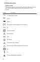
1.3 Safety information Symbols Used The following table lists the International Electrical Symbols. Some or all of these symbols may be used on the instrument or in this manual.
The following definitions apply to the terms “Warning” and “Caution”. • “Warning” identifies conditions and actions that may pose hazards to the user. • “Caution” identifies conditions and actions that may damage the instrument being used. Use the calibrator only as specified in this manual, otherwise injury and damage to the calibrator may occur. Warning To avoid possible electric shock or personal injury: • Do not apply more than the rated voltage. See specifications for supported ranges.
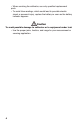
• When servicing the calibrator, use only specified replacement parts. • To avoid false readings, which could lead to possible electric shock or personal injury, replace the battery as soon as the battery indicator appears. Caution To avoid possible damage to calibrator or to equipment under test: • Use the proper jacks, function, and range for your measurement or sourcing application.
2. Calibrator Interface Figure 1 shows the location of the pressure controls, connection port and electrical inputs. Figure: external pressure supply MAX 120 PSI AIR SUPPLY 0-100 PSI OUTPUT -12-300 PSI PUMP -12-300 PSI MEASURE P1 P2 P3 P4 DPC-300A [P1] psi 30.
Figures 2A and 2B show the location of the keys. Table 2 describes the function of each key. Figure 2A Keypad Table 2 Key Functions No. Name Description 1 Function Keys These are soft keys used to configure the calibrator 2 ON/OFF Key This key is used to turn the calibrator on and off 3 ZERO Key This key is used to zero pressure measurements 4 Arrow Keys sed to control mA source/sim.
2.1 Calibrator Display The Calibrator Display consists of two regions: The menu bar (located along the bottom of the screen) is used to access a menu system. The main display (the rest) consists of up to three process measurement sub-regions. These sub-regions will henceforth be referred to as the UPPER, MIDDLE and LOWER displays. Figure 3 shows the location of the different display fields while table 3 describes them. [P1] 3 psi 30.000 mA MEASURE 100.00% 1 2 20.
2.1.2 Main Menu Functionality There are three options on the Menu, CONFIG, {Active Display} and MORE. The Main Menu is home for the menu display. 2.1.2.1 Setting the Active Display The active display is indicated by the center option on the Main Menu, pressing the F2 key will toggle the active display. 2.1.2.2 Setting Active Display Parameters To set the parameters of the active display use the CONFIG option to get to the Display Configuration Menu.
Table 4 Mode Concurrency Other Displays Active Display P[1] P[1] [EXT] P[1] ST [EXT] ST mA mA Loop Volts X X X X X X X X X X X X [EXT] X X P[1]ST X X [EXT]ST X X mA X X mA Loop X X Volts X X X X X X = valid mode 2.1.1.3 Accessing Other Menus Use the MORE option on the Main Menu to access the other menu functions. 2.2 Using the Backlight The backlight is controlled by the LIGHT softkey on the main menu.
arrow keys (F2 and F3 Keys). The sensor port should be open (vented) to atmosphere while performing this procedure. 2.4 Other Menu Controlled Functions There are many ‘sub-main’ menus that can be accessed through the MORE option of the Main Menu. A ‘sub-main’ menu contains three options. The first option is unique to the function. The second and third options of a ‘sub-main’ menu are always the same. The NEXT option leads to the next ‘sub-main’ menu and the DONE option returns home .
Max Menu, Contrast Adjustment menus and the Configuration Lock Menu. When the UNLOCK CFG option is chosen the configuration is unlocked and the menu display continues to the next sub-main menu. 2.4.3 Saving and Recalling Setups The calibrator will automatically save the current set-up for recall at power-up. Additionally 5 set-ups can be accessed through the SETUPS menu. Select the SETUPS option from the Setups Main Menu.
Figure 4 Menu Map 12
If SAVE or RECALL is selected use the arrow keys to select the setup location. Then use the save option to store the current set-up into the selected location or the recall option to recall the set-up stored in the selected location. The display menu will automatically go home. 2.4.4 Setting AutoShut-off Parameters The calibrator can be set to automatically shut-off after a selected number of minutes; this function can also be disabled.
Use the DONE option to save the changes and return home. When a display is deactivated its configuration is retained. When the display is activated its configuration is checked against the configurations of the other currently active displays, if the configurations are in conflict the recalled display’s configuration is modified to avoid the conflict. If all three displays are deactivated the LOWER display will come on automatically 2.4.
3. Set the pressure/vacuum selection knob to the desired function (+ for pressure and - for vacuum). 4. Close the vent knob. 5. Press the pump key and monitor the pressure rise (or vacuum generation) until you reach the desired pressure. Note: The motor speed will start slowly while the pressure is low (< 1 bar) to enable better control at low pressures. 6. The fine pressure adjustment enables the pressure to be set precisely. 7.
4.2 Measuring pressure with external modules The calibrator has a digital interface for external pressure modules. These modules are available for various ranges, including gauge, vacuum, differential and absolute pressure. The modules work seamlessly in conjunction with the calibrator. Simply plug them into the interface and select [EXT] (external sensor). Since the interface between the calibrator and the module is digital, the accuracy and display resolution is dependent on the module.
3. This selection can only be made in the lower display. Also, in source mode, the calibrator will generate 0 ... 24 mA using its own internal 24 V supply, whereas in simulation mode the calibrator acts as a 2-wire transmitter and requires an external 24 V supply. 4. Pressing any of the arrow keys will start the output mode and enable you to use the arrow keys to adjust the mA output.
Note: The display will indicate "OL" when the measured voltage exceeds the nominal range of voltage measurement (30 V). VOLTS PUMP 30.000 V CONFIG LOWER COM J1 MORE VOLTS /mA SWITCH TEST +24v DC J2 Test Item Up to DC 30 V J3 4.
5. Apply pressure with the pump slowly until the switch opens. Note: In the switch test mode the display update rate is increased to help capture changing pressure inputs. Even with this enhanced sample rate the device under test should be charged slowly with pressure in order to ensure accurate readings. 6. Once the switch is open, "OPEN" will be displayed; bleed the pump slowly until the pressure switch closes. 7.
9. Select the "NEW TEST" option to clear the data and perform another test. 10. Select the "DONE" option to end the test and return to the standard pressure setting. Example: [P1] ST will return to [P1]. The previous example uses a normally closed switch. The basic procedure is effectively the same for a normally open switch, the display will simply read "OPEN" instead of "CLOSE". 4.6 Calibrating transmitters 4.6.1 Using the mA measurement function The mA function enables the user to read out the 4 ...
4.6.2 Calibrating a pressure-to-current transmitter To calibrate a pressure-to-current transmitter (P/I), perform the following: 1. Connect the calibrator and the pump to the transmitter. 2. Apply pressure with the pump. 3. Measure the current output of the transmitter. 4. Ensure that the read value is correct. If it isn't, the transmitter must be adjusted.
MAX 120 PSI AIR SUPPLY 0-100 PSI OUTPUT -12-300 PSI PUMP -12-300 PSI MEASURE P1 P2 P3 P4 DPC-300A VOLTS 30.000 V PRESSURE MODULE FILTER CHARGE CONFIG LOWER MORE MARTEL ELECTRONICS F1 F2 FINE ADJUST / VENT F3 REGULATOR HOME PRESSURE ZERO VACUUM PUMP SELECTOR P3 PUMP Signal Output P2 COM J1 VOLTS /mA SWITCH TEST +24v DC J2 P4 MAIN SELECTOR +24V Power WARNING: VENT BEFORE SELECTION Pressure Transmitter Common J3 Figure 6 4.6.
Example: Suppose a pressure transmitter under test has a full scale range of 2 bar and gives a corresponding 4 ... 20 mA output signal. The user can programme in a 0 ... 2 bar pressure span into the calibrator and the calibrator will then calculate and display the deviation or %-Error value from the 4 ... 20 mA output. This then eliminates manual calculations. To use the "%-ERROR" function, perform the following: 1.
5. Use "SELECT" to scroll through the "UNIT" options, and select "NEXT" to move on. 6. Use the arrow keys to set the upper limit of the measuring range; select "DONE SET" when finished. 7. Use the arrow keys to set lower limit of the measuring range, and select "DONE SET" when finished. The "%-ERROR" mode will be ready to use.
5. Minimum and Maximum Storage Capability The 300 Series Pressure Calibrators have a min/max feature for capturing the minimum and maximum values of any displayed parameter. The min/max function can be accessed by stepping through the menu options until “min/max” is shown on the display above the F1 key. At this time, pressing the F1 key will toggle the display through the min/ max values that are stored in the min/max registers.
6. Remote Operation 6.1 Remote Interface The calibrator can be remotely controlled using a PC terminal, or by a computer program running the calibrator in an automated system. It uses an RS-232 serial port connection for remote operation. NOTE: To use the remote control option a custom RS-232 cable must be purchased from Martel (LEM232). To contact Martel refer to Section 1.1 of this manual.
from most office supply and computer stores. To connect the calibrator to the computer, attach the LEMO connector end of the cable to the pressure module port on the right side of the calibrator and the DB-9 connector to the RS-232 port on the computer. The calibrator should be turned off prior to making the connection and then turned on. To set up remote operation of the calibrator on the Windows Hyper Terminal, connected to a COM port on the PC as in Figure 23, use the following procedure: 1.
6.4 Using Commands 6.4.1 Command types Refer to the Section 10.5 on Remote Commands for all available commands. The calibrator may be controlled using commands and queries. All commands may be entered using upper or lower case. The commands are divided into the following categories: Calibrator Commands Only the calibrator uses these commands. For example VAL? asks for the values displayed on the calibrator display. Common Commands Standard commands used by most devices.
• Data is taken as 7-bit ASCII • The most significant data bit is ignored. • Upper or lower case is acceptable. 6.4.3 Response Data Types The data returned by the calibrator can be divided into four types: Integer For most computers and controllers they are decimal numbers ranging from -32768 to 32768. For example: FAULT? could return 110 Refer to the Error Codes table (Table 8) for more information on error codes. Floating Floating numbers have up to 15 significant figures and exponents.
6.5 Remote Commands and Error Codes The following tables list all commands, and their descriptions, that are accepted by the calibrator. Table 5: Common Commands Command Description *CLS (Clear status.) Clears the error queue. *IDN? I dentification query. Returns the manufacturer, model number, and firmware revision level of the Calibrator. *RST Resets the calibrator to the power up state. Table 6: Calibrator Commands Command Description DAMP Turns Damp on or off.
LOCKOUT Locks out the keypad of the calibrator in remote operation LO_ERR Sets the 0% of span limit for percent error mode LO_ERR Returns the 0% of span limit for percent error mode MOTOR_ON Turns the motor on. MOTOR_OFF Turns the motor off. MOTOR? Returns the current state of the Hart resistor OUT Set the calibrator to output the requested current. OUT? Returns the value of the current being simulated.
PERCENT Percent P1 P1 pressure measurement function ST_P1 Switchtest mode with P1 ST_EXT Switchtest mode with external module SOURCE Source state SIM Simulate state UPPER Designates Upper display V Voltage Table 8: Error Codes Error Number Error Description 100 A non-numeric entry was received where it should be a numeric entry 101 Too many digits entered 102 Invalid units or parameter value received 103 Entry is above the upper limit of the allowable range 104 Entry is below the
6.6.1 Common Commands *CLS Clears the error queue. Also terminates all pending operations. When writing programs, use before each procedure to avoid buffer overflow. *IDN? Returns the manufacturer, model number, and firmware revision of the Calibrator. For example: *IDN? will return MARTEL, DPC300A, 0, 1.00 6.6.2 Calibrator Commands DAMP Turns the dampening function on or off. For example: If you send DAMP ON this will turn the dampening function on.
For example, if a value for current output is entered that is bigger than the supported range (0-24mA) FAULT? Would return: 103 which is the code number for an entry over range. Refer to the Error Codes table for more information on error code numbers. ERROR _LOOP Turns loop power on or off in percent error mode. For example: To set loop power on send ERROR_LOOP ON. ERROR _LOOP? Returns the current state of loop power in percent error mode.
ERROR _ PORT? Returns the current pressure port for percent error mode. For example: If you send ERROR _PORT?, it will return P1 if the pressure port in percent error is [P1]. FUNC Sets the display indicated in argument one to the function indicated in argument 2. For example: To set the lower display to pressure mode send FUNC LOWER,[P1]. FUNC? Returns the current mode of all displays.
HI_ERR? Returns the 100% point for the percent error mode calculation. For example: If the 100% point is set to 100 psi, HI_ERR? would return 1.000000E+02, PSI . IO_STATE Sets the input/output/simulate state of the mA function of the calibrator. Does not put the calibrator in mA if it is not in it already. For example: If the calibrator is in mA simulate mode sending IO_ STATE MEASURE would put it in measure mode.
LO_ERR? Returns the 0% point for the percent error mode calculation. For example: If the 0% point is set to 20 psi, LO_ERR? would return 2.000000E+01, PSI . MOTOR_ON Turns the motor on. MOTOR_OFF Turns the motor off. MOTOR? Returns the state of the motor. For example: If the motor was on MOTOR? Would return ON. OUT This command also switches the calibrator into mA output mode. A number and a unit must be entered after the command.
PUMP_LIMIT Sets the approximate pressure in psi at which the pump will turn off. For example: PUMP_LIMIT 50 sets the approximate value that the pump will shutoff at to 50 psi PUMP_LIMIT? Returns the pump limit. Using the above example, PUMP_LIMIT? Would return: 50.000 REMOTE Puts the calibrator in remote mode. From the remote mode the user can still use the keypad to get back to local unless the command LOCKOUT was entered before REMOTE.
ST_OPEN? Returns the pressure that the switch opened at in the current pressure units. ST_DEAD? Returns deadband of the switch in the current pressure units. VAL? Returns the value of any measurement taking place on the upper and lower display. For example, if the upper display is measuring 5mA, and the lower display is measuring 10V, then VAL? will return: 5.000000E-03, A, 1.000000E+01, V ZERO_MEAS Zeroes the attached pressure module.
7. Specifications (15 °C to 35 °C unless otherwise noted.) General Instrument Setup Recall 5; last used on power-up Environmental Operating Temperature -10 °C to +50 °C Storage Temperature -20 °C to +60 °C Battery Type DC 16V, NiMH rechargeable battery Battery Life (fully-charged) Approx. 50 hours (only measurement or with external pressure supply) 125 pump cycles to 20 bar 300 pump cycles to 10 bar 1,000 pump cycles to 2 bar Physical Dimensions 15.25" x 12: x 7" (387.4 x 304.8 x 177.
8. Warranty Martel Electronics Corporation warrants all products against material defects and workmanship for a period of twelve (12) months after the date of shipment. Problems or defects that arise from misuse or abuse of the instrument are not covered. If any product is to be returned, a “Return Material Authorization” form can be obtained from our website www.martelcorp.com under customer service. You can also call 1-800-821-0023 to have a form faxed.
Ranges and Resolutions Range (PSI) 300 PSI / 20 Bar Burst Pressure (PSI) 2000 Proof Pressure (PSI) Engineering Unit 600 Factor Psi 1 300.00 bar 0.06894757 20.684 mbar 68.94757 20684 kPa 6.894757 2068.4 MPa .00689476 2.0684 kg/cm2 0.07030697 21.092 cmH2O @ 4°C 70.3089 21093 cmH2O @ 20°C 70.4336 21130 mmH2O @ 4 °C 703.089 N/A mmH2O @ 20°C 704.336 N/A inH2O @ 4°C 27.68067 8304.2 inH2O @ 20°C 27.72977 8318.9 inH2O @ 60°F 27.70759 8312.3 mmHg @ 0°C 51.
www.martelcorp.com e-mail: sales@martelcorp.com Tel: (603) 434-1433 800-821-0023 Fax: (603) 434-1653 Martel Electronics 3 Corporate Park Dr.