
Manual
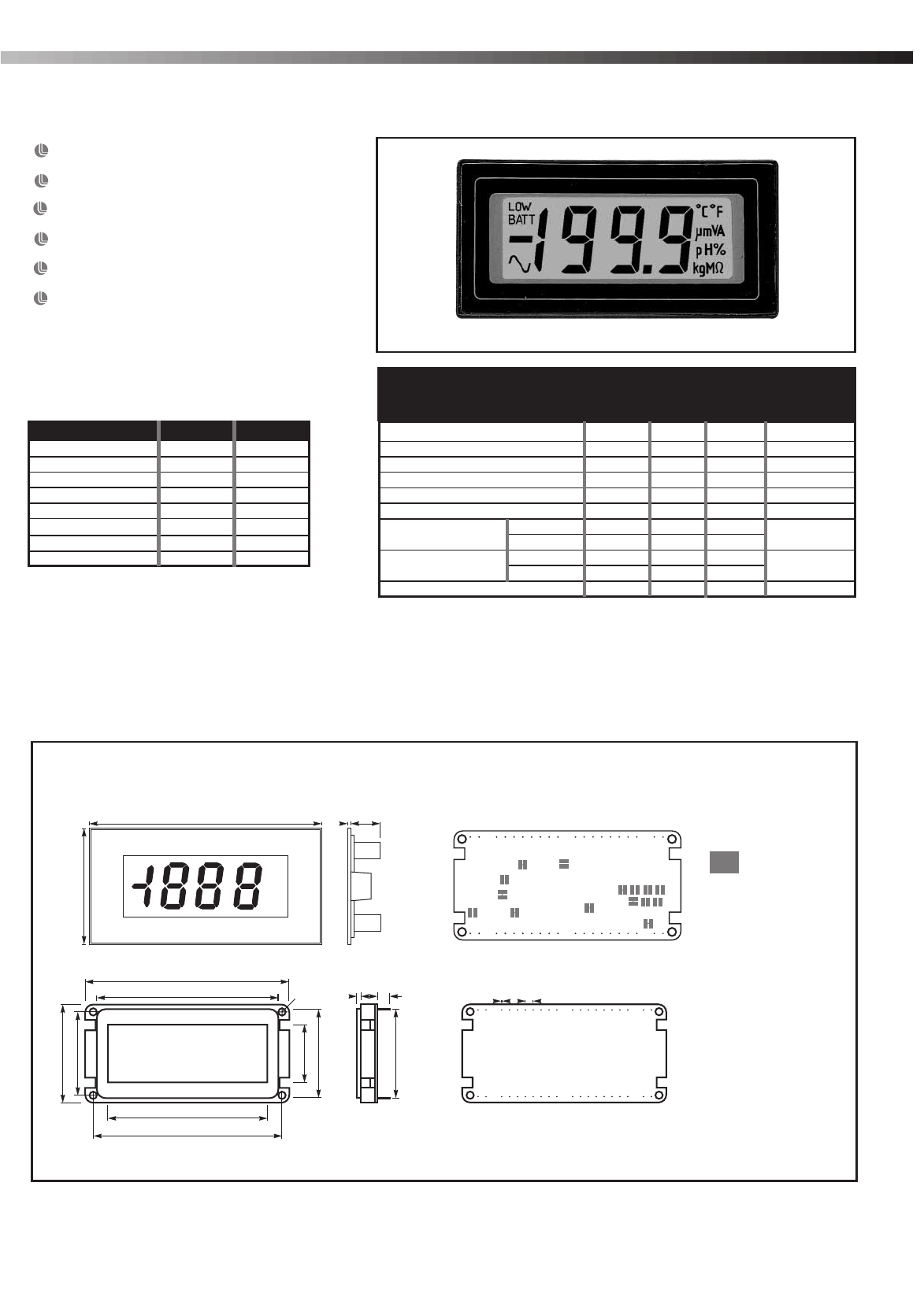
DIMENSIONS All dimensions in mm (inches)
Required F.S.R. Ra Rb
2V Note 910k 100k
20V Note 1M 10k
200V Note 1M 1k
2kV Note 1M 100R
200 A link 1k
2mA link 100R
20mA link 10R
200mA link 1R
µ
15mm (0.6“) Digit Height
Programmable Decimal Points
Auto-zero
Auto-polarity
200mV d.c. Full Scale Reading (F.S.R.)
Single Rail Version
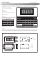
DPM 2000 3½ Digit LCD Module
The DPM 2000 uses advanced components and construction techniques to provide an unrivalled combination of high performance,
elegant appearance and low cost. The module uses a bandgap reference for extra temperature stability. For single rail operation, the
DPM 2000S features a built-in negative rail generator, enabling the meter to measure a signal referenced to its own power supply 0V.
Specification Min. Typ. Max. Unit
Accuracy (overall error) * 0.05 0.1 % (±1 count)
Linearity ±1 count
Sample rate 3 samples/sec
Operating temperature range 0 50 °C
Temperature s 30 ppm/°C
Supply DPM 2000 7.5 9 14
(V+ to V-) DPM 2000S 3.5 5 6.5
V
Supply current DPM 2000 150
DPM 2000S 500
A
Input leakage current (Vin = 0V) 1 10 pA
* To ensure maximum accuracy, re-calibrate periodically.
tability
voltage
µ
Stock Number
Standard Meter DPM 2000
Single Rail Version DPM 2000S
ON BOARD
SOLDER LINKS
SCALING RESISTORS
SCALING
NOTE
67.5 (2.66)
32.5 (1.28)
27.5 (1.08)
19.0 (0.75)
29.5 (1.16)
29.5 (1.16)
60.0 (2.36)
53.0 (2.09)
62.5 (2.46)
Ø2.50
(0.10)
cd e
fg
TEST
XB3
XDP
-5V
CLK
XG3
V+
RBG
REF-
REF+
E3
BP
AB
POL
REF HI
REF LO
COM
L
H
V-
I
I
+
-
pH
%
V
g
°F
°C
A
m
M
K
DP1
DP2
DP3
~
:
-
µ
Ω
Display in TEST mode
a. 1.00 (0.04)
b. 9.00 (0.35)
c. 1.25 (0.05)
d. 5.50 (0.22)
e. 4.00 (0.16)
f. 0.50 (0.02)
g. 2.54 (0.10)
LMP
8
13
12
H5
9
6
14
11 4 2 7
5
1
3
10
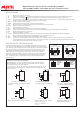
Rb
Ra
Two resistors Ra and Rb may be fitted in order to alter
the full scale reading (F.S.R) of the meter - see table.
The meter will need re-calibration.
Ensure that link 10 is open if fitting Ra.
SAFETY
To comply with the Low Voltage Directive (LVD 93/68/EEC), input voltages to the module’s pins must not exceed 60Vdc. If voltages to the measuring
inputs do exceed 60Vdc, then fit scaling resistors externally to the module. The user must ensure that the incorporation of the DPM into the user’s
equipment conforms to the relevant sections of BS EN 61010 (Safety Requirements for Electrical Equipment for Measuring, Control and Laboratory Use).
72.0 (2.83)
36.0 (1.42)
ab