
Instruction Manual
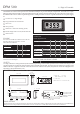


DIMENSIONS All dimensions in mm (inches)
Stock Number
Standard Meter DPM 500
Backlit Single Rail Version DPM 500S-BL
V
Aµ
CONNECTOR SOURCING GUIDE
METHOD 40 Pin DIL IC Socket
2
1
5
3
10
Rb Ra
13
12
11
8
9
4
7
12.5mm (0.5“) Digit Height
Programmable Decimal Points
Auto-zero
Auto-polarity
200mV d.c. Full Scale Reading (F.S.R.)
Backlit Single Rail Version (DPM 500S-BL)
Annunciators
DPM 500 3½ Digit LCD Module
Specification Min. Typ. Max. Unit
Accuracy (overall error)* 0.05 0.1 % (±1 count)
Linearity ±1 count
Sample rate 3 sample/sec
Operating temperature range 0 50 °C
Temperature stability 100 ppm/°C
Supply DPM 500 7.5 9 14
voltage DPM 500S-BL 3.5 5 6.5
Supply current DPM 500 150
DPM 500S-BL 250
Backlight Voltage 5 V
(DPM 500S-BL) Current 30 60 mA
Input leakage current (Vin = 0V) 1 10 pA
* To ensure maximum accuracy, re-calibrate periodically.
(not inc. backlighting)
SCALING
Two resistors Ra and Rb may be fitted in order to alter the
full scale reading (F.S.R.) of the meter - seetable.
Meter will need re-calibration.
Required F.S.R. Ra Rb
2V Note 910k 100k
20V Note 1M 10k
200V Note 1M 1k
2kV Note 1M 100R
200 A 0R 1k
2mA 0R 100R
20mA 0R 10R
200mA 0R 1R
µ
V+
V
m
µ
A
M
K
XB3
E3
AB
POL
~
-
:
°F
°C
60.0 (2.36)
45.0 (1.77)
Display in TEST mode
REAR VIEW
30.0 (1.18)
16.0 (0.63)
1.1
(0.04)
8.2
(0.32)
a
a. DPM 500 6.7 (0.26)
DPM 500S-BL 12.1 (0.48)
b. 4.80 (0.19)
DPM 500S-BL ONLY
ON-BOARD LINKS
OPTIONAL SCALING
RESISTORS
4.0 (0.16)
15.2 (0.60)
b
24.8 (0.98)
52 (2.05)
1.87
(0.07)
0.5
(0.02)
2.54
(0.1)
5.0
(0.19)
8.5 (0.33)
-
-
+
+
1
1
7
7
12
12
15
14
21
21
40
40
Panel cut-out = 57 x 27 (2.24 x 1.06)
PANEL FITTING
Fit the bezel to the front of the panel and locate the meter into the bezel from behind. Alternatively the meter and bezel may be assembled before
fitting to the front of the panel but care must be taken not to use excessive force. Finally fit the window into the front of the bezel.
20
20
V+
TEST
REF
HI
REF
LO
REF+
REF-
COM
IN HI
IN LO
BG
XDP
XG3
BP
DP1
DP2
DP3
V-
-5V
Hz
Ω
The DPM 500 uses advanced components and construction techniques to provide a uniquely compact unit. The meter is in a 40 pin
DIL integrated circuit format that can be plugged directly into a DIL socket or panel mounted using the snap in bezel. For single rail use,
the DPM 500S-BL features a built in negative rail generator, enabling the meter to measure a signal referenced to its own power supply
0V.
NOTE
Ensure link 10 iscut if fitting Ra.
-
+
°°
CF
µA
mV
kΩ
MHz
SAFETY
To comply with the Low Voltage Directive (LVD 93/68/EEC), input voltages to the module’s pins must not exceed 60Vdc. If voltages to the
measuring inputs do exceed 60Vdc, then fit scaling resistors externally to the module. The user must ensure that the incorporation of the
DPM into the user’s equipment conforms to the relevant sections of BS EN 61010 (Safety Requirements for Electrical Equipment for
Measuring, Control and Laboratory Use).