CONTENTS PRINT < > CONTENTS (ENGLISH) CONTENTS 1 UNPACKING 2 SERIAL NUMBER 3 FEATURES 4 WARNINGS 5 CAUTION 6 USER RESPONSIBILITY Loudspeaker Damage Shock Hazard Radio Interference 7 INTRODUCTION Input Level Attenuators On/Off Switch / Front Panel Indicators Plug In Card / Module Front Panel Function Switches Rear Panel Input Sockets Output Sockets / Ground Lift Switch Mains Voltage / Selection 8 PROTECTION SYSTEMS Fuse Information 9 INSTALLATION Mounting Cooling 10 OPERATING VOLTAGE Mains Connections Gr
< PRINT > GUIDES This equipment conforms to the requirements of the EMC Directive 89/336/EEC, amended by 92/31/EEC and 93/68/EEC and the requirements of the Low Voltage Directive 73/23/EEC, amended by 93/68/EEC Standards Applied 1 EMC Emission Immunity Electrical Safety EN55103 - 1: 1996 EN55103 - 2: 1996 EN60065: 1998 UNPACKING Every Martin Audio E1300 Amplifier is built to the highest standards and is thoroughly tested and inspected before it leaves the factory.
< PRINT > GUIDES 8. Bridgeable output stage 9. Switchable high pass filters, frequency selectable 10. Balanced XLR inputs with link outs, and dedicated sub bass outputs (when using plug in module) 11. Selectable input sensitivities and input mono sum facility 12. Speakon output sockets for Channel A, Channel B, and Bridge 4 WARNINGS Do not use this amplifier if the mains cable is damaged. Always operate this amplifier with the chassis ground wire connected to the electrical safety earth.
5 PRINT < > GUIDES CAUTION There are no user serviceable parts inside this amplifier. Removal of the cover by unauthorised personnel may invalidate warranty and will result in exposure to lethal high voltage and current. In the unlikely event of a fault developing within the E1300 refer servicing to qualified personnel only.
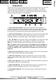
7 PRINT < > GUIDES INTRODUCTION Thank you for purchasing a Martin Audio power amplifier. This manual contains important information on operating your amplifier correctly and safely. Please take some time to read this manual and familiarise yourself with the advanced features of this amplifier. 1. Carry Protection Handle. Both handles can be used to carry the amplifier; they also act as a protection for the front panel and the controls.
PRINT < > GUIDES 9. Bridged Indicator. This illuminates when bridge mode is selected (function switch SW 5 is pushed IN). 10. Thermal Indicator. This indicates the thermal status of the amplifier. See page 19 for a full description. Plug In Card / Modules. The E1300 has the facility to accept a Martin Audio processing module. When fitted it replaces the removable panel on the front of the amplifier. It is connected to the main motherboard by a flexible ribbon cable. Front Panel Function switches.
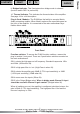
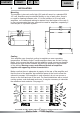
PRINT < > GUIDES Rear Panel 1. Fuse holder. The E1300 is fitted with a bayonet style 1/4 turn fuse holder. See pages 9 & 20 for fuse details and type. 2. Mains Power Connection. The E1300 is supplied with a 1.5M, 3 core captive cable. (See page 11). 3. Air Inlets. The E1300 uses forced air cooling for efficient operation. These inlets take in air which is exhausted from the front of the amplifier. 4, 5 and 6. Output Sockets. The amplifier is provided with 3 NL4 SPEAKON output sockets.
PRINT < > GUIDES 10. Line Level Output Socket. When a processing module is fitted, left and right sub bass signals can be routed to this output. See module operating instructions for a full description. 11. and 12 Input Link Sockets. 3 pin male XLR connectors are provided which are connected in parallel with the input sockets. These can be used for "daisy chaining" the signal to other amplifiers. Mains Voltage Selection.
8 PRINT < > GUIDES PROTECTION SYSTEMS The E1300 is provided with multiple protection circuits, these include current and dissipation limiting in the output stage, plus short circuit and high frequency protection. The power supply also has its own independent, start-up and shutdown hierarchy plus short circuit and over current protection. Fuse Information 1.
9 PRINT < > GUIDES INSTALLATION Mounting The amplifier is two-rack unit's high (2U) and will mount in a standard EIA 19" rack. Amplifiers may be stacked directly on top of each other; there is no need for spacing between units. If it is the intention to fill a rack with amplifiers, we recommend racking be started from the bottom of the rack. It is also recommended that rear supports be used for amplifiers, especially if used as part of a portable system.
10 PRINT < > GUIDES OPERATING VOLTAGE WARNING! A label above the mains power cable on the rear of the amplifier indicates the selected AC mains operating voltage. Connect the power cable only to the AC source referred to on the label. The warranty will not cover damage caused by connecting to the wrong type of AC mains. For converting a 230 volt amplifier to 115 volts or vice versa, contact Martin Audio Ltd or an approved Martin Audio dealer. Martin Audio E series amplifiers use primary switching, i.
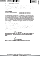
11 PRINT < > GUIDES POWER CONSUMPTION There are three ways to define the power/current consumption of the amplifier. First, the peak current draw at full sine wave power output. Under this condition the amplifier could thermally limit or blow the mains fuse, and is an unrealistic ‘normal’ use condition. To design a mains distribution system based on the current draw at full power would result in an over specified system.
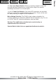
> GUIDES Power Table E1300 OUTPUT POWER E1300 MAINS INPUT POWER 1/3 POWER 1/8 POWER IDLE 8 Ohm 2X 400 680 400 117 4 Ohm 2X 720 1220 700 117 2 Ohm 2X 1000 1880 1200 117 1/3 Power level = Average power with music as programme source.
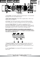
PRINT < > GUIDES The input impedance is sufficiently high to allow daisy chaining or multiple parallel input connections using the input 'Link' XLR. Balanced line (source and input): Unbalanced source with balanced input: To minimize hum in the audio, use balanced connections whenever possible. 14 All material © 2007. Martin Audio Ltd. Subject to change without notice.
13 < > GUIDES OUTPUT CONNECTIONS When a Martin Audio processing module is fitted it can be configured to output line level sub bass signals which may be fed to other amplifiers. The balanced signal appears on the 5 pin XLR connector on the rear of the amplifier. Pin Pin Pin Pin Pin 1 2 3 4 5 SCREEN CH,A + CH,A – CH,B + CH,B – The outputs of the module are not auto compensating, therefore when driving an unbalanced input use only the + output and screen.
PRINT < > GUIDES Keep the loudspeaker cables as short as possible and use good quality stranded cable. Do not use shielded wire, such as microphone or guitar cable. Remember that the loudspeaker cable robs the power of the amplifier in two ways; it increases the load impedance and also introduces resistive power losses. 15 OPERATING MODES Stereo For stereo dual channel operation ensure switch S4 (located behind the plug in card panel on the front of the amplifier) is in the "OUT" position.
16 PRINT < > GUIDES OPERATING PRECAUTIONS Make sure the power switch is "OFF" before making any input or output connections, installing a plug in module or operating any switches behind the removable panel / plug in module. Make sure that the AC mains are correct and that it is the same as that printed on the back of the amplifier. See pages 11 & 12 regarding operating voltage and power consumption.
PRINT < > GUIDES the amplifier to be used without severe hard clipping. The "card enable" LED indicates when a dedicated processing module is fitted in the amplifier. The remaining red "thermal" LED indicates the temperature status of the amplifier. The E1300 is fitted with a sophisticated thermal management system.
PRINT < > GUIDES When the amplifier has cooled back down to its normal operating temperature the red “max” LED’s and “thermal” LED’s will extinguish. The green and amber signal LED’s will become operational, and power to the loudspeakers will ramp up to the previous set level. DC Protection If more than ±5 volts appears on the amplifier outputs the power supply will shut down. Switch "OFF" the amplifier and check that the source of DC is not external to the amplifier i.e. controller sense lines etc.
18 PRINT < > GUIDES MAINTENANCE Under normal use the amplifier should give years of trouble free service. Periodically it may be necessary to clean the inside of the amplifier. (This should only be done by qualified service personnel). If you are using your amplifiers for heavy-duty use i.e. Concert touring or industrial music, it is recommended that you have your amplifier serviced every three years, purely as a preventative measure.
19 < PRINT > GUIDES WARRANTY General The E1300 Power amplifier is warranted to be free from defects in components and factory workmanship under normal use and service, for a period of one year from the date of original purchase.
20 < PRINT > GUIDES E1300 TECHNICAL SPECIFICATION INPUT IMPEDANCE 20K Ohms differential, 10K Ohms single ended INPUT SENSITIVITY Selectable 0.775mv (36dB gain) or 1.23V (32dB gain) FREQUENCY RESPONSE 17Hz - 46KHz + 0dB – 3dB POWER BANDWIDTH 10Hz - 40KHz + 0dB – 0.
< PRINT > GUIDES SIGNAL Pin 1 Ground lifted via 470R // 100nF. Options for pin 1 open circuit, and pin 1 connected directly to electrical earth INPUT CONNECTION POWER Captive 1.5M 3-core cable OUTPUT CONNECTIONS 3 x Speakon connectors, 1 x 5 pin XLR (stereo line level sub bass out) this is only active when a processing module is fitted (minimum load impedance 1K ohms) DIMENSIONS (incl. Handles) (W) 482mm x (H) 88mm x (D) 384.5mm (W) 19ins x (H) 3.5ins x (D) 15.1ins WEIGHT 9.5Kg (20.
CONTENTS PRINT < > E1300 GUIDES Amplifier Please Click here to return to main menu Please Click here to visit our website The Martin Experience Century Point, Halifax Road, Cressex Business Park, High Wycombe, Buckinghamshire HP12 3SL, England. Telephone: +44 (0)1494 535312 Facsimile: +44 (0)1494 438669 Web: www.martin-audio.com E-mail: info@martin-audio.com All material © 2007. Martin Audio Ltd. Subject to change without notice.
CONTENTS PRINT < > E1300 GUIDES Amplifier User’s Guide ENGLISH The Martin Experience All material © 2007. Martin Audio Ltd. Subject to change without notice.