CONTENTS < > ENGLISH ONLY GUIDES PRINT Wavefront Compact Series Applications Guide MARTIN AUDIO L O N D O N The Martin Experience All material © 2007. Martin Audio Ltd. Subject to change without notice.
CONTENTS < ENGLISH ONLY > GUIDES Wavefront Compact Series Applications Guide Contents Introduction Wavefront Compact Series Overview Section 1 W8C 3-way System Section 2 W8CT & W8CM Line Array System Section 3 W8CS Flown Subwoofer Section 4 WSX Folded Horn Subwoofer Section 5 W8L Series Line Array Systems Appendix A1 W8 3-way System A2 W8S HybridTM Subwoofer MARTIN AUDIO - APPLICATIONS GUIDE, WAVEFRONT COMPACT SERIES All material © 2007. Martin Audio Ltd.
CONTENTS < ENGLISH ONLY > GUIDES Introduction Wavefront Compact Series Overview Thank you for purchasing a Martin Audio Wavefront Compact Series system. Wavefront Compact Series products make up a coherent "toolkit" of compact, live sound enclosures covering a huge range of professional sound projects from high quality club installations to major touring and festival systems. Unpacking Each Martin Audio loudspeaker is built to the highest standard and thoroughly inspected before it leaves the factory.
CONTENTS < ENGLISH ONLY > GUIDES Cost effective rental The Martin Audio Wavefront Compact Series "tool kit" approach provides all the components required to assemble high quality, truck-friendly, quick deployment sound systems for applications ranging from small clubs, commercial and theatrical productions using floor placed W8Cs and W8CS’... to vast outdoor events with flown Longthrow and W8C clusters: MARTIN AUDIO - APPLICATIONS GUIDE, WAVEFRONT COMPACT SERIES All material © 2007. Martin Audio Ltd.
CONTENTS < > ENGLISH ONLY GUIDES Wavefront W8C systems are regularly used for audiences ranging from just a few hundred jazz devotees to thousands of arena concert-goers. Longthrow sections can increase touring system versatility even further and Longthrow/W8C combinations have been very successfully used to cater for festival audiences from hundreds of thousands to over two million at “Popestock” 2000. The Wavefront Compact series includes both flown and floor-standing subwoofers.
CONTENTS < > ENGLISH ONLY GUIDES Wavefront Longthrow W8CT & W8CM Line Array System The Wavefront Longthrow W8CT & W8CM system (Section 2) is a compact, very powerful, light weight, multiple horn line array loudspeaker system whose cabinets have the same footprint and flying points as Wavefront W8C and W8CS systems. Unlike odd-ball line arrays from other manufacturers, W8CTs and W8CMs have been designed to integrate seamlessly into the rest of the Wavefront family.
CONTENTS < > ENGLISH ONLY GUIDES Wavefront W8CS Flown Subwoofer The W8CS (Section 3) is a compact, light weight subwoofer that has the same cabinet footprint and flying points as the Wavefront W8C. It has been engineered to extend the W8C's performance to below 45Hz. The W8CS comprises a special high excursion driver coupled to an efficient mid-bass horn and sub-bass port.
CONTENTS < > ENGLISH ONLY GUIDES DX1 Loudspeaker Management System The Martin Audio DX1 (Section 1.5) is a very high performance, 2 input/ 6 output DSP-based controller providing crossover, protection, delay and alignment functions. It comes with factory plug'n'play presets for a wide range of Martin Audio product configurations including the Wavefront Compact family. It is ideal for combining Wavefront Compact products into seamless systems.
CONTENTS < ENGLISH ONLY > GUIDES PRINT Wavefront Compact Series Applications Guide Section 1 Wavefront W8C 3-Way System MARTIN AUDIO L O N D O N The Martin Experience All material © 2007. Martin Audio Ltd. Subject to change without notice.
CONTENTS < ENGLISH ONLY > GUIDES Section 1 Wavefront W8C 3-Way System Contents 1.1 Introduction 1.2 Specifications 1.3 Pin-outs and cabling 1.4 System patching 1.5 DX1 Loudspeaker Management System 1.6 Power amplifier recommendations 1.6.1 Martin Audio MA2.8 Power Amplifier Overview 1.7 General operational summary 1.8 Arraying and placement 1.9 Coverage calculations 1.10 W8Cs as front fills 1.11 W8Cs as side clusters 1.
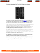
CONTENTS < ENGLISH ONLY > GUIDES Wavefront W8C 3-Way System 1.1 Introduction The award-winning Wavefront W8C 3-Way System is a very compact, light weight, high performance 3-way loudspeaker system in a trapezoidal cabinet. The Wavefront W8C integrates a horn-loaded 12" low-mid driver with a horn-loaded 6.5" high-mid driver and a horn-loaded 1" very high frequency compression driver. The 6.
CONTENTS < ENGLISH ONLY > GUIDES Maximum SPL: 129dB continuous, 135dB peak Impedance: Low-mid 8 ohms nominal High-mid 16 ohms nominal High 16 ohms nominal Coverage (-6dB): 55º horizontal, 30º vertical Crossover: 750Hz, 3.5kHz Connectors: 2 x Neutrik NL8, 2 x EP8 Cabinet construction: Birch Ply Cabinet finish: Slate textured paint Protective grille: Perforated steel Grille finish: Grey paint Dimensions (incl wheels): (W) 562mm x (H) 799mm x (D) 925mm (W) 22.1ins x (H) 31.
CONTENTS < ENGLISH ONLY > GUIDES 1.3 Pin-outs and cabling W8C Connector type W8C mode EP8 NL8 W8C Active* W8C Passive* 1 -1 Low Mid - Low Mid - 2 +1 Low Mid + Low Mid + 3 -2 High Mid - High Mid/High - 4 +2 High Mid + High Mid/High + 5 -3 High - n/c 6 +3 High + n/c 7 -4 n/c n/c 8 +4 n/c n/c (*see Section 1.5 for details of the connector panel Active/Passive switch MARTIN AUDIO - APPLICATIONS GUIDE, WAVEFRONT COMPACT SERIES All material © 2007. Martin Audio Ltd.
CONTENTS < ENGLISH ONLY > GUIDES 1.3.
CONTENTS < ENGLISH ONLY > GUIDES without feedback and without stressing its mechanical, electrical or electro-acoustic components. 3) Be divided into easily understood sections (eg Main, midfield, downfill etc) and clearly labelled so that adjustments may be made quickly and efficiently. The schematic above shows a simple system using a Martin Audio DX1 Loudspeaker Management System configured as a 2 x 3way crossover controlling W8Cs switched for passive high-mid/high sections and W8CS subwoofers.
CONTENTS < ENGLISH ONLY > GUIDES Recommended W8C pairs: Inner Farfield Inner Midfield Inner Nearfield Inner Downfield Outer Farfield Outer Midfield Outer Nearfield Outer Downfill Controller channel allocations The whole cluster may be controlled from just ½ a Martin Audio DX1 controller set up for 3-way operation. See Section 1.5 for further DX1 information. Power amplifier channel allocations There are 8 pairs of W8Cs each requiring high, high-mid & low-mid power amplifier channels.
CONTENTS < ENGLISH ONLY > GUIDES Initial inner level settings Initial inner level settings can be calculated for each row as follows: MARTIN AUDIO - APPLICATIONS GUIDE, WAVEFRONT COMPACT SERIES All material © 2007. Martin Audio Ltd. Subject to change without notice.
CONTENTS < ENGLISH ONLY > GUIDES The farfield inner power amplifier channels are the reference... Initial outer level settings Similarly, initial outer level settings can be calculated for each row as follows: Again, the farfield inner amplifier setting (0dB) is used as a reference... In a fairly small, wide, fan-shaped venue with heavily raked seating, we may require the following amplifier channel settings: MARTIN AUDIO - APPLICATIONS GUIDE, WAVEFRONT COMPACT SERIES All material © 2007.
CONTENTS < ENGLISH ONLY > GUIDES The attenuation rate shown here is 2dB per cluster row. The actual rate of vertical attenuation will depend on the cluster height which in turn will depend on the rake of the seats. High clusters are further from the audience at the front and require less nearfield & downfill attenuation. The lower the cluster, the greater the required attenuation rate. Again, the vertical layout is...
CONTENTS < > ENGLISH ONLY GUIDES 1.5 DX1 Loudspeaker Management System Martin Audio can provide factory set configuration cards for a variety of off-the-shelf crossover systems (contact your dealer or Martin Audio Ltd for further information) but the Martin Audio DX1 Loudspeaker Management System is strongly recommended for all new Wavefront system designs. The Martin Audio DX1 is a very high performance DSP-based controller and provides crossover, protection, delay and alignment functions.
CONTENTS < ENGLISH ONLY > GUIDES Ø Improved high-mid/high limiter action Three Martin Audio MA2.8 power amplifiers will drive four W8Cs (assuming W8Cs driven in pairs). Passive Mode (DX1 factory presets 20 & 22) In Passive mode the high-mid and high drivers share a power amplifier channel via a passive high-mid/high crossover network built into the loudspeaker cabinet. This mode offers a slightly reduced performance but requires only two power amplifier channels per 3-way W8C system. Two MA2.
CONTENTS < ENGLISH ONLY > GUIDES See Section 2.4 for a full system example. 1.5.1 DX1 specifications Inputs CMRR Outputs Min. Load Max. Level Frequency Resp. Dynamic Range Distortion Maximum Delay Output gain Input gain 2 electronically balanced. >10k ohms >65dB 50Hz - 10kHz 6 electronically balanced. <60 ohms 600 ohm +20dBm into 600 ohm load ±0.5dB 20Hz - 20kHz >110dB 20Hz -20kHz. Unwtd <0.02% @ 1kHz, +18dBm 650mS. (Increment 2.6uS) adjustable +15dB to -40dB in 0.
CONTENTS < ENGLISH ONLY > GUIDES 1.5.2 DX1 Output Gain and Limiter settings for W8Cs Standardising on one good model of power amplifier (preferably the Martin Audio MA2.8) and correctly set-up controller (preferably the Martin Audio DX1) will provide the most dynamic system performance and protection whilst simplifying design and reducing spares inventories.
CONTENTS < ENGLISH ONLY > GUIDES Balancing the system using gain controls in the signal path before the power amplifiers will cause the higher signal level upper row of a big cluster to start limiting before the lower signal levels downfills causing tonal changes at the mix position. Limiter settings The Rated Power specifications in Section 1.2 show that the maximum allowable power dissipation depends on the driver/s being driven.
CONTENTS < ENGLISH ONLY > GUIDES long enough to be obvious to listeners or cause driver overheating. It is quite normal to see amplifier clip indicators on the odd programme peak but continuous clipping would indicate a cable short circuit, wrong controller settings, excessive power amplifier gain or low mains voltage. The following DX1 output limiter settings will avoid voice coil overheating and minimise amplifier clipping for high quality, trouble free operation.
CONTENTS < ENGLISH ONLY > GUIDES Use lower limiter settings (or more loudspeakers!) if your power amplifiers indicate clipping on more than just the odd peak. Excessive clipping may also be caused by cable faults or an inadequate mains supply. See Section 1.6 The DX1 may be user-programmed to many more touring and fixed installation configurations based on its 2 input + sum, 6 output matrix. This operation is best completed by an audio technician who is familiar with DSP-based pro-audio.
CONTENTS < ENGLISH ONLY > GUIDES Martin Audio MA Series Power Amplifiers Martin Audio MA Series amplifiers have regulated rails so it is quite permissible to use slightly overpowered models - with suitably set controller limiters - without risking uncontrolled power bursts. The MA series power amplifiers’ regulated power rails also ensure maximum performance under the real-world concert conditions of less-than-optimum mains supplies and parallel cabinets. See Section 1.6.1.
CONTENTS < ENGLISH ONLY > GUIDES Gain or level settings Gain switches If you are lucky enough to have amplifiers with user gain switches, set them all to identical positions. A voltage gain in the range 23-33dB will provide a good balance of system headroom and noise (assuming professional audio equipment is in use FOH).
CONTENTS < ENGLISH ONLY > GUIDES Features Ø Ø Ø Ø Ø Ø Switch mode power supply Superior sonic performance Light weight Advanced protection circuits Efficient copper cooling system Minimum load switches (MLStm) The MA2.8 power amplifier has been designed to combine reliability and high power output with sonic excellence. Utilising an advanced switch mode power supply, the MA2.8 yields a very high power-to-weight ratio in a lightweight, 2U package. See MA2.
CONTENTS < ENGLISH ONLY > GUIDES drops by 20%. Minimum Load Switches (MLS™) Because the SMPS is regulated, the maximum power available for the output stages can be adjusted without increased heat dissipation or efficiency loss. This allows the user to match the output power with the loudspeaker impedance. Protection The MA2.8 amplifier has many advanced protection features that will protect both the amplifier and the speakers connected to it, under fault conditions.
CONTENTS < ENGLISH ONLY > GUIDES MA2.8 Specifications Input Impedance Gain select switch CMRR at 1kHz Output impedance at 1kHz Power Bandwidth Slew rate Hum/Noise Channel Separation Mains Operating Voltage Protection Distortion THD 20Hz - 20kHz and 1W – 1000W THD at 1kHz and 1100W DIM 30 at 500W CCIF (13 and 14 kHz) at 500W SMPTE (60Hz and 7kHz) at 500W Power Matrix 20kohms (balanced) 10kohms single ended 38dB (I/P sens 0.775V), 32dB (I/P sens 1.55V) >50dB 0.
CONTENTS < ENGLISH ONLY > GUIDES 1.7 General operational summary 1) Always use the same model system controller and power amplifier for a particular Wavefront product. This avoids confusion caused by different controller topologies and power amplifiers voltage gains. 2) It is common practice to use mixing console matrix outputs as loudspeaker section controls.
CONTENTS < ENGLISH ONLY > GUIDES Single W8C on W8CS subwoofer This very compact stack may be used for as one side of a main system for a folk band concert in a small venue, one corner of a small dance floor system, stage side fills, stage drum fills, front fills etc. SAFETY REMINDER! Stacks should always be safety strapped to allow for high winds, over-exuberant artists, crowd indicipline, scenery movements etc.
CONTENTS < ENGLISH ONLY > GUIDES Flown systems overview Flown clusters are recommended for very high power music systems covering large venues to ensure adequate coverage without excessive levels at the front of the venue. Wavefront series products are fitted with MAN load-certified flying points and are designed to comply with the 12:1 safety factor specified by the German VBG70 standard when used with compatible 12:1 flying systems.
CONTENTS < ENGLISH ONLY > GUIDES Cabinets may be fitted with rear hinge back plates to allow removable hinges to be slotted in place. These hinge assemblies provide a more rigid rear cabinet alignment. For further information please refer to the Martin Audio Wavefront 8 Flying System User Guide. Rigging Schools! Rigging should not be undertaken by untrained or unqualified personnel. Suitable rigging training sessions may be arranged by calling Martin Audio Ltd on +44 (0)1494 535312.
CONTENTS < ENGLISH ONLY > GUIDES OK No, No, No!!! i) NEVER suspend one cabinet from the lower flying point of the cabinet above. ii) NEVER suspend standard cabinets horizontally. Two Wavefront Compact W8Cs correctly rigged using upper key-holes only MARTIN AUDIO - APPLICATIONS GUIDE, WAVEFRONT COMPACT SERIES All material © 2007. Martin Audio Ltd. Subject to change without notice.
CONTENTS < ENGLISH ONLY > GUIDES 1.9 Coverage calculations Single W8C column Here is an example of a 1-wide, 3 deep column of Wavefront W8Cs. The horizontal coverage is, of course, that of a single W8C ie 55º.
CONTENTS < ENGLISH ONLY > GUIDES Double W8C column Here is a 2 wide, 3 deep column of Wavefront W8Cs.
CONTENTS < ENGLISH ONLY > GUIDES Wide coverage cluster 4 or 6 wide, 4 deep W8C clusters may be rigged for very wide coverage.
CONTENTS < ENGLISH ONLY > GUIDES Circular cluster Two 6-wide, 4 deep W8C clusters with 30º horizontal splay angles and 20º vertical splay angles may be flown back-to-back to provide full 360º horizontal x 90º vertical coverage for ice shows, for example. Column View Note that the 90º coverage allows foldback to be provided to the ice-dancers. The centre hole may be filled by flying a smaller cabinet underneath the main cluster.
CONTENTS < ENGLISH ONLY > GUIDES 1.10 W8Cs as front fills Wavefront W8Cs may be used as stage apron fills for high power rock concerts. When carefully placed on radii converging at the centre downstage (lead vocal) area and sychronised with the main PA downfills, these apron fills don't just balance the subwoofers. They can focus vocals and add a detailed quality that can be beneficial right out to the mix position.
CONTENTS < > ENGLISH ONLY GUIDES Apron fill delay line setting = t downfill - t apron fill Apron fill gain setting wrt downfill gain = 20log10(t downfill ÷ t apron fill) dB 1.11 W8Cs as side clusters A Wavefront Longthrow (See Section 2) centre cluster may be used with W8C downfills for efficient operatic and orchestral amplification.
CONTENTS < ENGLISH ONLY > GUIDES 1.12 W8Cs in distributed (delay) systems Wavefront W8C Compacts make very good high power distributed systems or delay elements as they project sound smoothly and efficiently without local off-axis lobing. For good overall coverage, delays are best driven in mono for most of the show although computer controlled matrix mixes may be considered for panning spot effects around the venue.
CONTENTS < > ENGLISH ONLY GUIDES Synchronising flown central delays Synchronising flown outer delays Ideally, the sound should be perceived as coming from the stage over the whole audience area - which means that all the delay loudspeakers should be aligned with the stage opening. In practice, sight line, follow spot and camera shot restrictions will affect placement for heavily raked seating areas and intelligent compromises will need to be made.
CONTENTS < > ENGLISH ONLY GUIDES Aiming delay tower loudspeakers Multiple delay tower loudspeakers should be tilted so that they aim towards head height at the next tower to mask off-axis tower leakage and to minimise multiple arrivals further out. Synchronising multiple tower systems (not to scale) Small delay time errors are inevitable where delay towers are located in audience areas (eg on a football field) due to the three dimensional geometry involved.
CONTENTS < ENGLISH ONLY > GUIDES Wavefront Compact Series Applications Guide Section 2 Wavefront Longthrow W8CT & W8CM Line Array System MARTIN AUDIO L O N D O N The Martin Experience All material © 2007. Martin Audio Ltd. Subject to change without notice.
CONTENTS < ENGLISH ONLY > GUIDES Section 2 Wavefront Longthrow W8CT & W8CM Line Array System Contents 2.1 Introduction 2.2 Specifications 2.3 Pin-outs and cabling 2.4 System patching 2.5 DX1 gain & limiter settings 2.6 Power amplifier recommendations 2.7 General system reminders 2.8 Coverage 2.9 Further examples Section 2a Climatic effects on sound propagation 2a.1 Introduction 2a.2 Wind effects 2a.3 Temperature effects 2a.
CONTENTS < ENGLISH ONLY > GUIDES Wavefront Longthrow W8CT & W8CM Line Array System 2.1 Introduction The Martin Audio Wavefront Longthrow W8CT & W8CM Line Array System is a compact, light weight, very high power, multiple horn line array loudspeaker system in a trapezoidal cabinet sharing design concepts and footprints with the rest of the popular Martin Audio Wavefront Compact family.
CONTENTS < ENGLISH ONLY > GUIDES 2.2 Specifications W8CT Type: Dedicated longthrow high-mid/high enclosure Frequency response: 750Hz-18kHz +/- 3dB Drivers: 3 x 6.
CONTENTS < ENGLISH ONLY > GUIDES Coverage (-6dB): 55º horizontal, Line vertical (see Section 2.8) Crossover: 120Hz, 750Hz Connectors: 2 x Neutrik NL8 Cabinet construction: Birch Ply Cabinet finish: Slate textured paint Protective grille: Perforated steel Grille finish: Grey paint Dimensions (incl wheels): (W) 562mm x (H) 799mm x (D) 925mm (W) 22.1ins x (H) 31.5ins x (D) 36.4ins Flown weight: 72kg (158lb).
CONTENTS < ENGLISH ONLY > GUIDES 2.3 Pin-outs and cabling W8CT & W8CM NL8 W8CT W8CM -1 Link through Low Mid - +1 Link through Low Mid + -2 High Mid - Link through +2 High Mid + Link through -3 High 1 - Link through +3 High 1 + Link through -4 High 2 - Link through +4 High 2 + Link through (See Section 1.3 for connector pin-out drawing) 2.3.
CONTENTS < ENGLISH ONLY > GUIDES Cable run vs copper core cross sectional area One W8CT or W8CT/CM combination Two W8CTs in parallel or two W8CT/CM combinations in parallel at the cluster. Up to 50m 4mm² (or 2x 2.5mm²cores in parallel) Up to 100m 10mm² (or 2x 4mm²cores in parallel) 10mm² (or 2x 4mm²cores in parallel) Not recommended but use 2x 10mm² cores in parallel if you must. Q. Why the odd sizes? A. Loudspeaker cables are available in a limited range of standard copper core sizes ie. 1.
CONTENTS < > ENGLISH ONLY GUIDES The above schematic shows a typical system incorporating a row of Wavefront Longthrow W8CT & W8CM elements with Wavefront Compact W8Cs and W8CS’ crossed over as flown mid-bass sections to augment floor stacked WSX subwoofers. The system uses Martin Audio DX1 Loudspeaker Management Systems configured as 5-way crossovers.
CONTENTS < ENGLISH ONLY > GUIDES For further notes on system patching, including cluster sub-section controller and amplifier allocations see Section 1.4. 2.5 DX1 gain & limiter settings Standardising on one good model of power amplifier (preferably the Martin Audio MA2.8) and correctly set-up controller (preferably the Martin Audio DX1) will provide the most dynamic system performance and protection whilst simplifying design and reducing spares inventories.
CONTENTS < ENGLISH ONLY > GUIDES Cluster balance (eg inner-to-outer) should be adjusted at the power amplifier controls to maintain limiter tracking. See Section 2.7. Balancing the system using gain controls in the signal path before the power amplifiers is not recommended as it will cause the higher signal level upper rows of a big cluster to start limiting before the lower signal levels downfills causing tonal changes at the mix position. Limiter settings The Rated Power specifications in Section 2.
CONTENTS < ENGLISH ONLY > GUIDES These attack times allow the power amplifiers to clip momentarily - but not for long enough to be obvious to listeners or cause driver overheating. It is quite normal to see amplifier clip indicators on the odd programme peak but continuous clipping would indicate a cable short circuit, wrong controller settings, excessive power amplifier gain or low mains voltage.
CONTENTS < ENGLISH ONLY > GUIDES 2.6 Power amplifier recommendations Wavefront Longthrow loudspeakers have been designed and manufactured for very high performance over great distances. They are very easy - particularly if power amplifier racks and controllers are standardised within a system.
CONTENTS < ENGLISH ONLY > GUIDES Amplifier load tolerance An efficient loudspeaker in live concert conditions can act as a surprisingly dynamic and complex load. Most modern touring power amplifiers claim 2 Ohm capabilities but make sure your amplifier is also capable of driving reactive (ie inductive or capacitive) loads without prematurely clipping or developing output stage crossover distortion.
CONTENTS < ENGLISH ONLY > GUIDES power amplifier level control advanced in sequence to check system operation and patching. Assuming that controller output levels and limiters have been set as tabulated in Section 2.5, power amplifier level controls should be set to full (fully clockwise) for loudspeaker sections requiring the strongest drive. Amplifiers, driving nearer-field sections within the same cluster, may be backed off as required for smooth coverage.
CONTENTS < ENGLISH ONLY > GUIDES 2.8 Coverage W8CT and W8CMs are designed to be flown in vertical line arrays to provide a combination of W8C-compatible 55º horizontal coverage with tight vertical control. The vertical coverage of a single W8CT is approximately 7.5º in the upper midrange. When dead-hung, as illustrated below, the vertical coverage narrows with increasing cluster height following the classic law for multi-element line arrays. * = speed of sound (m/s).Varies with temp.
CONTENTS < ENGLISH ONLY > GUIDES Straight column gain and coverage The following table shows typical Longthrow high-mid/high gain (wrt a single Wavefront W8C) plus the mid and high frequency vertical coverage provided by various straight vertical line arrays. W8CTs in high-mid/high gain (wrt single W8C) vertical coverage (-6dB points) high-mid high 1 (single row) 2 (double row) 4 6 8 10 9.5dB 16dB 22dB 25dB 28dB 30dB 7.42º 3.72º 1.86º 1.24º 0.93º 0.74º 3.70º 1.86º 0.93º 0.62º 0.46º 0.
CONTENTS < > ENGLISH ONLY GUIDES Unfortunately, continuous vertical columns are rarely visually acceptable particularly where the audience wraps around a thrust stage and sight lines are critical. In such cases, shorter Longthrow columns may be flown in combination with Wavefront W8C midfields and downfills. Martin Audio/M.A.N.
CONTENTS < ENGLISH ONLY > GUIDES IMPORTANT NOTES! Rigging should not be undertaken by untrained or unqualified personnel. Suitable rigging training sessions may be arranged by calling Martin Audio Ltd on +44 (0)1494 535312. Flown systems examples Wavefront cluster examples are included in this manual to illustrate recommended loudspeaker combinations and splay angles only.
CONTENTS < ENGLISH ONLY > GUIDES 2.9 Further examples Wavefront Longthrow columns may be horizontally arrayed for wide coverage: 30 30 30 30 30 30 30 30 (left & right clusters will be mirror image) High-mid/high horizontal coverage would be 1/2 left W8CT + 30º + 30º + 1/2 right W8CT = one W8CT +30º + 30º = 55º + 60º = 115º. MARTIN AUDIO - APPLICATIONS GUIDE, WAVEFRONT COMPACT SERIES All material © 2007. Martin Audio Ltd. Subject to change without notice.
CONTENTS < ENGLISH ONLY > GUIDES 2.9.1 Flying with W8CS’ Wavefront Longthrow columns may be flown with Wavefront W8CS’ (Section 3). The W8CS’ may be configured as fullbass systems - to leave the floor free for camera tracks, for example - or as a mid-bass section to augment floor-stacked WSXs where a large, standing audience is expected forward of the mix position.
CONTENTS < ENGLISH ONLY > GUIDES PRINT 2.9.2 Flying with W8Cs Wavefront Longthrow columns may be flown with Wavefront Compact W8C midfield and downfill sections. The following example shows a wide coverage Longthrow system with W8C midfield and downfill sections. Note that a double (vertically tightpacked) row of W8Cs has been flown as the midfield section. Vertically tightpacking these W8Cs extends their forward throw to help smooth the transition from Wavefront Longthrow to Wavefront W8C.
CONTENTS < ENGLISH ONLY > GUIDES A typical arena gain set-up may be as follows: Main Longthrow section Double W8C midfield section W8C downfills -12dB to -6dB -6dB to 0dB -4dB to 0dB 2.9.3 Adding Longthrow elements to W8C/W8CS clusters Wavefront Longthrow elements may be added to conventional W8C/CS clusters for larger venues, to improve overall sound projection to, for example, upper rear seats.
CONTENTS < ENGLISH ONLY > GUIDES Climatic effects on sound propagation 2a.1 Introduction When working in large venues or outdoors we should always remember that sound propagates through air and is affected by air temperature, humidity and wind. The most audible of these effects is wind as it can vary dramatically in less than a second causing rapidly swept filter effects that change middle and high frequency content into incoherent noise.
CONTENTS < ENGLISH ONLY > GUIDES their opinions or compare the system’s high frequency sound quality with a pair of high quality mix position monitors delayed back to the PA. The PA should sound warmer and more punchy but should never sound brighter than good monitors unless the man with the cheque book wants it that way. 5) Always get trusted sound crew members to walk the field during the show.
CONTENTS < ENGLISH ONLY > GUIDES Spaced, parallel loudspeakers will comb (add or subtract their outputs) depending on their distance or time offset from us (see Section 4.10). A 150mm/0.5ms offset at the listening position will cause nulls at 1KHz, 3KHz, 5KHz, 7KHz, 9KHz, 11KHz etc but we wouldn't be aware of the combing under casual listening conditions because we are used to listening to natural sounds in the presence of multiple arrivals (echoes) and our ear-brain system adapts to them.
CONTENTS < ENGLISH ONLY > GUIDES Wind gradient Air movement is slowed by friction so wind is usually lighter near the ground than it is higher up. Ground level wind speeds can vary from over 90% of the main wind speed in the daytime, when the air is being mixed by being warmed by the ground, to under 30% at night, when air - cooled by the ground - looses buoyancy. This varying wind speed with height is called the wind gradient.
CONTENTS < ENGLISH ONLY > GUIDES Local winds Air absorbs very little heat from the sun's rays. It is indirectly heated by contact with warm surfaces. It also relies on contact with cooling surfaces to lose heat. A local, anabatic wind can be set up by air rising up a slope warmed by the morning sun. The same slope may cool the air at night causing it to flow down hill to form a katabatic wind.
CONTENTS < ENGLISH ONLY > GUIDES Local winds may be even more erratic in showery weather. Dramatic down-drafts of cold air may occur causing local squalls. Graph showing main wind speed (dark colour) and gusts (light colour) over several hours The above main wind and gust plot shows that gusts can be more erratic in nature and several times stronger than the main wind. Their effects will be far more audible than a steady wind.
CONTENTS < ENGLISH ONLY > GUIDES 2a.3 Temperature effects The speed of sound varies with air temperature: This means that the speed of sound can vary from 331.5m/s to 354.9m/s between 0ºC and +40ºC. Temperature Gradient As mentioned in Section 2a.2, air is a poor heat conductor and relies on its contact with surfaces to heat up and cool down. On a clear, warm, sunny day the ground will warm low level air and the atmosphere will heat up, by convection, from bottom to top.
CONTENTS < ENGLISH ONLY > GUIDES If the sky remains clear after sunset, the ground will cool and draw heat from the air in contact with it. Air nearest the ground may get cooler than the air above it. In the absence of wind, this cool air may stay near the ground on a still night. 60m 50m 40m 30m 20m Temperature inversion 10m 0m 0˚C 10˚C 20˚C The same "inverse temperature gradient" can form above ice rinks and in most indoor venues.
CONTENTS < ENGLISH ONLY > GUIDES 0.3dB/m 10KHz 0.2dB/m 6KHz 0.1dB/m 3KHz 1.5KHz 0dB/m Absorption coefficient 0 10% 20% 30% 40% 50% 60% 70% 80% 90% Relative Humidity In this example, high-mid and high frequency air absorption characteristics are quite complex at low relative humidity. Mid frequency absorption increases with increasing humidity, reaches maximum attenuation at about 5% RH and then starts to drop again.
CONTENTS < ENGLISH ONLY > GUIDES PRINT Wavefront Compact Series Applications Guide Section 3 Wavefront W8CS Flown Subwoofer MARTIN AUDIO L O N D O N The Martin Experience All material © 2007. Martin Audio Ltd. Subject to change without notice.
CONTENTS < ENGLISH ONLY > GUIDES Section 3 Wavefront W8CS Flown Subwoofer Contents 3.1 Introduction 3.2 Specifications 3.3 Pin-outs and cabling 3.4 System patching 3.5 DX1 Loudspeaker Management System 3.6 Power amplifier recommendations 3.6.1 Martin Audio MA4.2 Power Amplifier Overview 3.7 Adding W8CS’ to flown W8C systems MARTIN AUDIO - APPLICATIONS GUIDE, WAVEFRONT COMPACT SERIES All material © 2007. Martin Audio Ltd. Subject to change without notice.
CONTENTS < ENGLISH ONLY > GUIDES Wavefront W8CS Flown Subwoofer 3.1 Introduction The Martin Audio Wavefront W8CS Flown Subwoofer comprises a special 15" high excursion driver coupled to an efficient mid-bass horn with a sub-bass port. This unique combination gives the W8CS the characteristic punch of a horn-loaded system with the low frequency bass extension of a reflex enclosure. The W8CS is a compact, light weight system in a trapezoidal cabinet.
CONTENTS < ENGLISH ONLY > GUIDES Maximum SPL: 132dB continuous, 138dB peak Impedance: 8 ohms nominal Connectors: 2 x Neutrik NL8 Cabinet construction: Birch Ply Cabinet finish: Slate textured paint Protective grille: Perforated steel Grille finish: Grey paint Dimensions (inc wheels): (W) 562mm x (H) 799mm x (D) 925mm (W) 22.1ins x (H) 31.5ins x (D) 36.4ins Flown weight: 61kg (134lb).
CONTENTS < ENGLISH ONLY > GUIDES 3.3 Pin-outs and cabling W8CS NL8 W8CS -1 Driver - +1 Driver + -2 Driver - +2 Driver + -3 n/c +3 n/c -4 n/c +4 n/c (See Section 1.3 for connector pin-out drawing) 3.3.
CONTENTS < ENGLISH ONLY > GUIDES Cable run vs copper core cross sectional area Up to 50m Up to 100m Single W8CS Two W8CS’ paralleled at the cluster. 2.5mm² 6mm² 6mm² (or 2 x 2.5mm² cores in parallel) 10mm² (or 2 x 6mm² cores in parallel) Q. Why the odd sizes? A. Loudspeaker cables are available in a limited range of standard copper core sizes ie. 1.5mm², 2.5mm², 4mm², 6mm², 10mm² and 35mm². 3.4 System patching Refer to Section 1.4 and Section 2.
CONTENTS < ENGLISH ONLY > GUIDES 3.5 DX1 Loudspeaker Management System Refer to Section 1.5 for general information on the Martin Audio DX1 Loudspeaker Management System including configuration examples. 3.5.1 DX1 Output Gain and Limiter settings for W8CS’ Standardising on one good model of power amplifier (preferably the Martin Audio MA4.
CONTENTS < ENGLISH ONLY > GUIDES Cluster balance (eg farfield-to-midfield or inner-to-outer) should be adjusted at the power amplifier controls to maintain limiter tracking. See Section 3.7. Balancing the system using gain controls in the signal path before the power amplifiers is not recommended as it will cause the higher signal level upper rows of a big cluster to start limiting before the lower signal levels downfills causing tonal changes at the mix position.
CONTENTS < ENGLISH ONLY > GUIDES W8CS - assuming 800Wcont - 1600Wpk into 8Ω Ω power amplifiers: Best-fit Amplifier Example Amplifier Amplifier Sensitivity Gain dBu Vrms dB Crown MA5002VZ (0.775v) Martin MA4.2** (41dB) Crest CA18 (x115) Crown MA3600VZ (0.775v) -2 -1 -1 -1 0 +1 +2 +3 QSC PL236/PL236A (36dB) +4 +5 +6 +7 Martin MA4.2** (32dB) +8 Crest 8001 (x40) +8 Crest 9001 (x40) +8 QSC PL236A (32dB) +8 +9 +10 +11 +12 +13 Crown MA3600VZ (26dB) +14 Crown MA5002VZ (26dB) +14 QSC PL236A (26dB) +14 0.
CONTENTS < ENGLISH ONLY > GUIDES 3.6 Power amplifier recommendations The Wavefront Compact Subwoofer has been designed and manufactured for very high performance but will not give that performance unless power amplifiers are chosen and used intelligently.
CONTENTS < ENGLISH ONLY > GUIDES Power reserve Most power amplifier specifications are based on bench measurements made using stable, high current mains supplies and well defined loads. Amplifiers sound best when they have plenty of current in reserve for percussive peaks and sustained bass notes. 1) Try to ensure that the mains supply stays within the amplifier manufacturer’s specified range from no load to maximum load.
CONTENTS < ENGLISH ONLY > GUIDES may be backed off as required for smooth coverage. This process will ensure that the cluster coverage remains balanced during limiting. Rack mounting As with main W8C systems, always leave a 1U space between big subwoofer power amplifiers and controllers. Although most modern amplifiers don’t radiate significant fields it's better to play safe and keep the system free from hum & buzz. Rear supports are recommended.
CONTENTS < ENGLISH ONLY > GUIDES See MA4.2 Power Amplifier User's Guide for detailed operating instructions. Cooling System The Martin Audio MA4.2 amplifier runs very cool due to a special patented copper cooling system. The amplifier’s bi-polar output devices are mounted directly onto a copper heat sink (copper conducts heat twice as efficiently as aluminium) and maximum heat dissipation is achieved by turbulent airflow over the heatsink’s geometric fins. The MA4.
CONTENTS < ENGLISH ONLY > GUIDES Protection The MA4.2 amplifier has many advanced protection features that will protect both the amplifier and the speakers connected to it, under fault conditions. All protection circuits are independent and inaudible in normal use. Clip Limiters Clip limiters prevent dangerous clipped signals reaching the speaker. They work by monitoring the output to check for signals not present at the input i.e.distortion.
CONTENTS < ENGLISH ONLY > GUIDES MA4.2 Specifications Input Impedance Gain select switch CMRR at 1KHz Output impedance at 1KHz Power Bandwidth Slew rate Hum/Noise Channel Separation Mains Operating Voltage Protection Distortion THD 20Hz - 20kHz and 1W – 1000W THD at 1 kHz and 2000W DIM 30 at 500W CCIF (13 and 14kHz) at 500W SMPTE (60Hz and 7kHz) at 500W 20kohms (balanced) 10kohms single ended 41dB (I/P sens 0.775V), 32dB (I/P sens 2.26V) >50dB <0.
CONTENTS < > ENGLISH ONLY GUIDES 3.7 Adding W8CS’ to flown W8C systems Although the Wavefront W8C is often used as a base for smaller floor-stacked or stage-stacked systems (see Section 1.8), flying W8CS’ with main W8C systems can keep the floor tidy and free up floor space for scenery, TV camera tracks etc. As mentioned earlier, very large outdoor festival crowds will absorb mid-bass from low-profile, ground stacked subwoofers.
CONTENTS < ENGLISH ONLY > GUIDES standard W8C cluster extending its low frequency response to below 45Hz. This configuration can be very efficient as it uses the rest of the cluster as a baffle, increasing forward projection allowing high gain before feedback.
CONTENTS < ENGLISH ONLY > GUIDES W8CS’ flown in rows with W8Cs 30 30 30 30 30 30 20 20 20 20 30 30 30 30 30 30 20 20 30 20 30 20 30 Multiple rows of W8CS’ increase low frequency headroom for higher power rock, dance club applications. Note that flying W8CS’ in rows keeps clusters relatively narrow where width is at a premium. Coverage would be 145º horizontal x 70º vertical.
CONTENTS < ENGLISH ONLY > GUIDES as flown mid-bass elements (crossed in at 60Hz and out at 160Hz) to augment floorstacked WSXs working as low subs below 60Hz. Refer to Section 2.4. Power amplifier monitoring at real-world gigs have shown that half of the total system power is demanded between 60Hz & 160Hz during heavy rock and dance music.
CONTENTS < > ENGLISH ONLY GUIDES providing good vertical control for minimum roof excitation. W8CS’ may be flown as fullbass where floor space is required for TV cameras or may be configured as flown mid-bass elements to complement floor-stacked WSXs. For further information on suitable Wavefront subwoofer systems and a brief tutorial on bass stack sizes and shapes vs coverage see Section 4. MARTIN AUDIO - APPLICATIONS GUIDE, WAVEFRONT COMPACT SERIES All material © 2007. Martin Audio Ltd.
CONTENTS < ENGLISH ONLY > GUIDES PRINT Wavefront Compact Series Applications Guide Section 4 Wavefront WSX Folded Horn Subwoofer MARTIN AUDIO L O N D O N The Martin Experience All material © 2007. Martin Audio Ltd. Subject to change without notice.
CONTENTS < ENGLISH ONLY > GUIDES Section 4 Wavefront WSX Folded Horn Subwoofer Contents 4.1 Introduction 4.2 Specifications 4.3 Pin-outs and cabling 4.4 System patching 4.5 DX1 Loudspeaker Management System 4.6 Power amplifier recommendations 4.7 Placement 4.8 WSX application examples 4.9 Further examples 4.10 Spaced systems 4.11 Electronic steering MARTIN AUDIO - APPLICATIONS GUIDE, WAVEFRONT COMPACT SERIES All material © 2007. Martin Audio Ltd. Subject to change without notice.
CONTENTS < ENGLISH ONLY > GUIDES Wavefront WSX Folded Horn Subwoofer 4.1 Introduction The powerful WSX folded horn subwoofer is designed to complement Wavefront Series W8C touring systems to provide deep bass with maximum efficiency, speed and impact. Its classic Martin ‘S’ shaped folded horn is over 7 feet (2.1m) long and couples a powerful 18” (460mm) long excursion driver to the airload with a modified hyperbolic expansion law. 4.
CONTENTS < ENGLISH ONLY > GUIDES 4.3 Pin-outs and cabling WSX NL8 WSX -1 Driver - +1 Driver + -2 Driver - +2 Driver + -3 n/c +3 n/c -4 n/c +4 n/c (See Section 1.3 for connector pin-out drawing) MARTIN AUDIO - APPLICATIONS GUIDE, WAVEFRONT COMPACT SERIES All material © 2007. Martin Audio Ltd. Subject to change without notice.
CONTENTS < ENGLISH ONLY > GUIDES 4.3.1 Cable and panel connector part numbers Please note the following part numbers when ordering loudspeaker connectors to make up cables and patch panels Neutrik NL connectors NL8FC NL8MPR NL8MM 8 pole cable (female) 8 pole panel (male) 8 pole inline coupler (male-male) Connectors should be kept in good, clean, uncorroded condition to ensure full, undistorted loudspeaker performance. Corroded or damaged pins and sockets can cause severe distortion or loss of signal.
CONTENTS < > ENGLISH ONLY GUIDES Loudspeaker Management System. The following illustrates a DX1 set up to control an active (3-way) Wavefront W8C system with floor-stacked WSXs augmented by W8CS’ configured as flown mid-bass sections. Augmenting WSXs with flown W8CS’ as mid-bass sections eliminates the problem of mid-bass absorption experienced with densely packed standing crowds. 4.5 DX1 Loudspeaker Management System Refer to Section 1.
CONTENTS < ENGLISH ONLY > GUIDES WSX - assuming 600Wcont - 1200Wpk into 8Ω Ω power amplifiers: Best-fit Amplifier Example Initial DX1 Amplifier Amplifier Output GAIN Sensitivity Gain When used as: Sub-bass Full bass dBu Vrms dB (>60Hz) (>160Hz) dB dB Crown MA5002VZ (0.775v) -2 0.62 42 -4 -9 Martin MA4.2** (41dB) -1 0.69 41 -3 -8 Crest CA18 (x115) -1 0.69 41 -3 -8 Crown MA3600VZ (0.775v) -1 0.69 41 -3 -8 0 0.77 40 -2 -7 +1 0.87 39 -1 -6 +2 0.98 38 0 -5 +3 1.09 37 +1 -4 QSC PL236/236A (36dB) +4 1.
CONTENTS < ENGLISH ONLY > GUIDES To ensure transparent limiter operation without obvious distortion or pumping, the DX1 limiter attack and release times are factory preset to be inversely proportional to the subwoofer's high pass frequency. These attack times allow the power amplifiers to clip momentarily but not for long enough to be obvious to listeners or cause driver overheating.
CONTENTS < ENGLISH ONLY > GUIDES NOTE! Use lower settings (or more subwoofers!) if your power amplifiers indicate clipping on more than just the odd peak. Excessive clipping may also be caused by inadequate power amplifier reserve or an inadequate mains supply. See Section 4.6. 4.6 Power amplifier recommendations The Wavefront WSX Subwoofer has been designed and manufactured for very high performance but will not give that performance unless power amplifiers are chosen and used intelligently.
CONTENTS < ENGLISH ONLY > GUIDES Amplifier load tolerance An efficient subwoofer system in live concert conditions can act as a surprisingly dynamic and complex load. Most modern touring power amplifiers claim 2 ohm capabilities but make sure your amplifier is also capable of driving reactive (ie inductive or capacitive) loads without prematurely clipping or developing output stage crossover distortion.
CONTENTS < ENGLISH ONLY > GUIDES Level controls The front panel level controls should be turned down (fully counter clockwise) until FOH-to-Amp rack lines have been checked and controllers have been set to suit the power amplifiers to be used (see Section 4.5.1). Music should be used to check that controllers are receiving and sending the appropriate signal bands and then each power amplifier level control advanced in sequence to check system operation and patching.
CONTENTS < > ENGLISH ONLY GUIDES WSX horns flare away from the label end. They can be symmetrically coupled by placing them label-to-label … Symmetrically coupled 2-wide columns show a slight improvement in mid-bass amplitude and polar response - but the effect becomes insignificant in large, flat fronted arrays or widely spaced stage apron systems. 2-wide symmetrical columns of WSXs may be horizontally arrayed just like main cluster systems.
CONTENTS < ENGLISH ONLY > GUIDES 4.7.1 Array shapes vs coverage WSXs may be stacked and arrayed to increase sound pressure and tailor coverage. The sound pressure increase is intuitive but the significance of subwoofer array shapes and sizes is often overlooked.
CONTENTS < ENGLISH ONLY > GUIDES 4.7.2 Coverage angle for tightly packed flat fronted arrays -6dB Coverage Here is a simplified formula for calculating the main coverage angle of a tightly packed flat fronted array. * = approximate speed of sound in m/s. Varies with temperature (see Section 2a). Arcsin means “the angle whose sin is ...” Flat fronted cluster coverage patterns will be confined to one main lobe whose midbass crossover directivity is proportional to the size of the cluster.
CONTENTS < ENGLISH ONLY > GUIDES A note on coverage nulls It is useful to be able to calculate where these first response nulls will occur for various frequencies as they indicate areas where coverage, transient response and directional information would be poor without fill systems. For symmetrical arrays nulls will occur either side of the on-axis line.
CONTENTS < ENGLISH ONLY > GUIDES Vertical Boundary effects A solid floor will act as a reflector. This will cause a vertical stack to perform as if it were double the length, giving a useful low frequency boost accompanied by a narrower, more complex polar response. For instance, an 8 high ground-based stack of WSXs will act like the top half of a 16 high stack. At 80Hz its smoothest vertical coverage will be from the floor to its own height (4.6m) + 16.5º.
CONTENTS < ENGLISH ONLY > GUIDES WSXs Wide (standing upright) Horizontal coverage 40Hz 80Hz 160Hz 3 4 8 16 Wide Wide Wide 69º Wide Wide 69º 33º 98º 69º 33º 16º With WSXs standing upright, flat fronted cluster coverage patterns will be confined to one main lobe whose mid-bass crossover width is inversely proportional to the size of the cluster as long as horizontal gaps are less than 500mm. ♦ Use wide arrays for long shots.
CONTENTS < > ENGLISH ONLY GUIDES The following formula gives the pressure ratio p(h) (wrt to the on-axis pressure) for any off-axis angle of a regularly spaced linear array: Far field polar patterns can be quite complicated - even for a simple pair of subwoofers driven in unison. Wide spacing will cause off axis irregularities (combing) because time offsets start to become significant. See Section 4.10 for a more detailed explanation.
CONTENTS < ENGLISH ONLY > GUIDES The following tables give the maximum recommended gap (between WSX sides) for the relevant frequency range. WSXs standing upright Gap Smooth coverage range 0.5m 1.0m 2.0m 38 - 160Hz 38 - 110Hz 38 - 80Hz WSXs lying horizontally Gap Smooth coverage range 0.0m 0.5m 1.0m 2.0m 38 - 160Hz 38 - 115Hz 38 - 86Hz 38 - 60Hz To avoid combing... ♦ Keep horizontal gaps below 1m for upright WSXs ♦ Keeps horizontal gaps below 0.2m for horizontal WSXs 4.7.
CONTENTS < ENGLISH ONLY > GUIDES WSXs Wide (On sides. Splayed with Radius = width) Horizontal coverage 40Hz 80Hz 160Hz 2 4 8 16 Wide 90º 60º 30º 90º 60º 30º 36º 60º 30º 36º 40º Note that lower frequencies remain focussed when large arrays are used with large radii. Smaller systems with small radii will widen coverage at all frequencies but may cause low frequency build-up on thrust and island stages.
CONTENTS < > ENGLISH ONLY GUIDES 4.8 WSX application examples The following sketches show how WSXs may be deployed for a wide range of productions and types of venue. All productions and venues present their own unique requirements and these examples are intended as a template or starting point for your own specific design. Examples 1 and 2 show typical set-ups for smaller venues.
CONTENTS < > ENGLISH ONLY GUIDES (3) WSX set-up for very high power dance/rock production in narrow arena Gives narrow horizontal & vertical coverage up to 120Hz - allowing for ground effects. Example 3 shows a very high power dance or rock set-up for a narrow “shoe box” venue. Note the four-wide left and right WSX arrays for tight horizontal control and the more tightly packed apron systems for central focusing.
CONTENTS < ENGLISH ONLY > GUIDES (5) Alternative set-up for wide venues Splayed WSX arrays for wide horizontal coverage. Example 5 shows a set-up for a TV shoot in a similar wide venue where sight-lines are critical. Note the lower profile, splayed left and right WSX arrays. 4.8.
CONTENTS < ENGLISH ONLY > GUIDES 4.9 Further examples Thrust stages Examples 6 and 7 show typical set-ups for large, thrust stage productions. (6) WSX set-up for high power variety/orchestral production on large thrust stage front view side view Gives medium vertical & wide horizontal coverage up to 120Hz for audience on 3 sides - allowing for ground effects.
CONTENTS < ENGLISH ONLY > GUIDES (7) WSX set-up for very high power dance/rock production on large thrust stage front view side view Gives narrow vertical & wide horizontal coverage up to 120Hz for audience on 3 sides - allowing for ground effects - with tighter apron WSX spacing for more coherent nearfield mid-bass coverage and punch.
CONTENTS < ENGLISH ONLY > GUIDES 4.10 Spaced systems Whenever two or more loudspeaker systems are fed with the same signal and their coverage overlaps, sound addition and subtraction will take place depending on the listener’s position. In the following example, the off-axis listener may hear delayed sound from the right hand system.
CONTENTS < ENGLISH ONLY > GUIDES Addition & Subtraction The above shows how two pairs of sine waves (with identical amplitude and frequency characteristics) will sum. Pair (a) are in phase and add. Pair (b) are out of phase and cancel. MARTIN AUDIO - APPLICATIONS GUIDE, WAVEFRONT COMPACT SERIES All material © 2007. Martin Audio Ltd. Subject to change without notice.
CONTENTS < > ENGLISH ONLY GUIDES Polar variations with frequency Whether particular frequency components add or subtract in the far field will depend on the loudspeaker system spacing, the angular offset of the listener with respect to the centre line, and the wavelength. The following polar responses show what happens when subwoofers are placed 8.
CONTENTS < > ENGLISH ONLY GUIDES changed dramatically around the sides. There are now strong lobes at the sides because the spacing is now an even number of half-wavelengths at this particular frequency. These lobes could cause low frequency feedback problems on stage with the high microphone gains used for orchestral low string (cello, double bass) sections or for “unplugged” performances. 60Hz At 60Hz the spacing is an odd number of half-wavelengths again so we see side nulls again.
CONTENTS < ENGLISH ONLY > GUIDES 40 Hz reduced spacing The above shows what happens at 40Hz if we reduce the spacing between the subwoofers to 4.3m. We get better central coverage without 40Hz side lobes - adequate for long, narrow “shoe-box” venues but wider coverage would be required for most arenas.
CONTENTS < ENGLISH ONLY > GUIDES In the following example, listeners over a wide central area will hear a warm bass note rich in harmonics whereas those around the sides (in line with the subwoofers at 90º) will hear less of the fundamental but more of the harmonics whose full wavelengths coincide with the subwoofer spacing. Listeners in the 60º zone will hear the note at a reduced level and may be more aware of room reverberation because the direct-to-reverberation ratio would be poorer for that note.
CONTENTS < > ENGLISH ONLY GUIDES Note that it is important to keep the subwoofers tightly packed to avoid polar anomolies caused by spacing. Procedure The normal procedure is to measure the angle from the top of the vertical subwoofer stack to the highest/most distant seats (using an inclinometer) and to calculate the required delay increment with the formula shown. Example We wish to project bass/mid-bass punch to stadium balcony seats 30º higher than the top of our WSX stacks.
CONTENTS < ENGLISH ONLY > GUIDES This means that our delay increment (in ms) = tan 30º x 0.572 x 1000 340 = 0.577 x 0.572 x 2.94 = 0.97mS or 970uS. The following delay line taps would be required for the above system: t0 t1 t2 t3 t4 t5 t6 = = = = = = = 0ms 0.97mS 1.94mS 2.91mS 3.88mS 4.85mS 5.82mS Going further It is possible to apply electronic shaping to horizontal arrays. For instance, it is common to use curved main clusters for smooth mid and high frequency coverage.
CONTENTS < > ENGLISH ONLY GUIDES All material © 2007. Martin Audio Ltd. Subject to change without notice.
CONTENTS < ENGLISH ONLY > GUIDES Section 5 Application Guide Wavefront W8L Series Line Arrays W8L, W8LC & W8LM plus W8LS and WLX Sub-woofers Simply need controller and amplifier rack information? Skip to sections 5.10, 5.11 & 5.12 5.1 Introduction 5.2 Specifications, outline drawings and performance plots 5.3 Classic line array behavior 5.4 How many do I need? 5.5 ViewPointtm 3.03 and System control 5.6 Horizontal considerations 5.7 Sub-woofers and Front Fills 5.8 Climatic effects 5.
CONTENTS < ENGLISH ONLY > GUIDES Wavefront W8L Series Line Arrays 5.1 Introduction Martin Audio W8L Series line arrays are next generation line array systems which combine innovative loudspeaker design techniques with line array technology to produce a family of very powerful line arrays with extended frequency response, smooth coverage and maximum dynamic impact.
CONTENTS < > ENGLISH ONLY GUIDES with a range of Martin Audio sub-woofers including the Martin Audio W8LS direct radiating sub-woofer system or the Martin Audio WLX horn-loaded & ported (Hybridtm) sub-woofer system. See Section 5.7.
CONTENTS < > ENGLISH ONLY GUIDES W8L rear rigging Caution: W8L Series columns should be rigged and flown by professional riggers or trained personnel under professional riggers' supervision. Flying professional loudspeaker systems is not a job for amateurs! See the appropriate Flying System User Manual for further details. All material © 2007. Martin Audio Ltd. Subject to change without notice.
CONTENTS < ENGLISH ONLY > GUIDES 5.2 W8L, W8LC, W8LM line array element specifications (single enclosure) Specification Type Frequency Resp (±3dB) Hor Coverage (-6dB) (-10dB) Vert Coverage (-6dB) Driver complement Rated Power W8L W8LC W8LM Full-range 3-way line array element 50Hz-18KHz 90deg 120deg 7.5deg LF: 1 x 15” Hybridtm horn-loaded cone drivers Compact 3-way line array element 60Hz-18KHz 90deg 120deg 7.
CONTENTS < ENGLISH ONLY > GUIDES 134dB cont., 140dB peak. 129dB cont., 135dB peak. 125dB cont., 131dB peak. HF: 136dB cont., 142dB peak. HF: 129dB cont., 135dB peak. LF: 8 ohms LF: 8 ohms MF: 8 ohms MF: 8 ohms Passive 124dB cont., 130dB peak. Bi-amplified LF+MF: 12 ohms HF: 12 ohms HF: 8 ohms HF: 8 ohms Nominal Impedance Crossover Connectors Enclosure Finish Grille Dimensions mm inches (*incl wheelboard) Weight (incl.
CONTENTS < > ENGLISH ONLY GUIDES W8L & W8LS outline dimensions (W8L shown) All material © 2007. Martin Audio Ltd. Subject to change without notice.
CONTENTS < > ENGLISH ONLY GUIDES W8LC outline dimensions All material © 2007. Martin Audio Ltd. Subject to change without notice.
CONTENTS < > ENGLISH ONLY GUIDES W8LM outline dimensions All material © 2007. Martin Audio Ltd. Subject to change without notice.
CONTENTS < > ENGLISH ONLY GUIDES W8LX outline dimensions All material © 2007. Martin Audio Ltd. Subject to change without notice.
CONTENTS < ENGLISH ONLY > GUIDES W8L polar plot W8L beamwidth plot All material © 2007. Martin Audio Ltd. Subject to change without notice.
CONTENTS < ENGLISH ONLY > GUIDES W8LC polar plot W8LC beamwidth plot All material © 2007. Martin Audio Ltd. Subject to change without notice.
CONTENTS < ENGLISH ONLY > GUIDES W8LM polar plot W8LM beamwidth plot All material © 2007. Martin Audio Ltd. Subject to change without notice.
CONTENTS < > ENGLISH ONLY GUIDES 5.3 Classic line array behavior Although the vertical coverage of a single point source may be wide, when arrayed in a straight line, multiple sources vector sum to form a tight vertical coverage pattern that narrows with increasing cluster height and frequency following the classic law for multiple source line arrays. * = speed of sound (m/s).Varies with temp.
CONTENTS < ENGLISH ONLY > GUIDES Point Sources The effects of geometric spreading are well known for the three idealised sound sources; the point, line and plane. The behaviour of each is based solely on the assumption that, in a homogeneous medium, sound propagation from a single point source is purely spherical. Thus the sound energy in any particular direction is inversely proportional to the increasing surface area of the sphere.
CONTENTS < > ENGLISH ONLY GUIDES SPL = SWL(line) - 10log(4 p r) For a line source this results in only a 3dB reduction in sound pressure level per doubling of distance in the nearfield . . . But note: This nearfield -3dB/doubling distance varies with frequency and straight line array length Plane Sources For a plane source (e.g. a flat wall of sub-woofers), integrating an infinite number of point sources distributed in two dimensions produces a flat surface.
CONTENTS < > ENGLISH ONLY GUIDES Stacked general purpose horns vs low curvature line array elements The following illustrations compare the poor coverage characteristics of vertically stacked general purpose horns with the properly designed low curvature horns found in the W8L Series line arrays.
CONTENTS < > ENGLISH ONLY GUIDES All material © 2007. Martin Audio Ltd. Subject to change without notice.
CONTENTS < > ENGLISH ONLY GUIDES The listener hears the vector sum of more and more cabinets as he moves further away from a straight line array. These increasing contributions partially compensate for the normal reduction in sound pressure with distance from source. Note that farfield spl levels will increase towards the centre of the array where more elements add.
CONTENTS < > ENGLISH ONLY GUIDES Irregular coverage from a J-Shaped Array Smoother coverage from a Martin Audio Progressive Curvature Array ViewPointtm calculates the maximum summation point (near the top of a progressively curved array) and aims this towards the furthest listening area. A progressive curvature array’s HF coverage weakens dramatically above the maximum summation point so this point is regarded as the Coverage Stop – see Section 5.5.12 All material © 2007. Martin Audio Ltd.
CONTENTS < ENGLISH ONLY > GUIDES 5.4 How many do I need? There are four major factors to take into account when specifying line array columns for a specific application. 1) 2) 3) 4) Will I need delays? Very important - see Section 5.9. Spectral Balance - the minimum column length required for spectral balance over the full audience distance or just beyond the 1st delays. Maximum SPL - the number & model required to achieve maximum spl. Horizontal Coverage – see Section 5.6. 5.4.
CONTENTS < > ENGLISH ONLY GUIDES The transition distance is not the system’s maximum throw. It is the distance that the system’s near-field characteristic will reach – or, if you prefer, the 3dB per doubling of distance attenuation range (ignoring air absorption). Beyond this distance the attenuation rate will increase to 6dB/doubling of distance (ignoring air absorption). The transition distance can be thought of as the distance that the line array’s advantageous low attenuation rate will reach.
CONTENTS < ENGLISH ONLY > GUIDES Model and quantity for a balanced spectral response A spectrally balanced system will provide a useful far-field response within an octave of the product’s LF and HF specification. A system’s LF response may be enhanced by extending the effective column length with sub-woofers flown above or stacked immediately below the array. HF air absorption is the dominant factor beyond 50m. Be cautious about specifying very long throw systems where the air may be dry (e.g.
CONTENTS < > ENGLISH ONLY GUIDES Example 1 12 x W8L (at 1°) per side festival system in side wings for 100m throw Example 2 16 x W8L per side arena system Upper 12 cabinets at 1 & 2° for 100m throw All material © 2007. Martin Audio Ltd. Subject to change without notice.
CONTENTS < > ENGLISH ONLY GUIDES Example 3 12 x W8LM per side 41m concert hall system All material © 2007. Martin Audio Ltd. Subject to change without notice.
CONTENTS < ENGLISH ONLY > GUIDES 5.4.2 Maximum far-field on-axis SPL Calculations Simplified maximum far-field on-axis spl estimates for a single column may be made using the following simple arithmetic and look-up tables . . .
CONTENTS < ENGLISH ONLY > GUIDES W8LM W8LC W8L Max dB spl Max dB spl Max dB spl cont. pk cont. pk cont. pk 1 134 140 129 135 125 131 2 140 146 135 141 131 137 4 145 151 140 146 136 142 6 148 154 143 149 139 145 8 150 156 145 151 141 147 Effective source spl (referred to 1m) vs model & quantity Quantity (splayed at 1°) W8LM W8LC W8L Max dB spl Max dB spl Max dB spl cont. pk cont. pk cont.
CONTENTS < ENGLISH ONLY > GUIDES Horizontal off-axis attenuation Off-axis figures will be less than single column on-axis figures at mid and high frequencies as follows: Horizontal off-axis attenuation -3dB -6dB -10dB W8L (± off-axis angle) 22.5° 45° 60° W8LC (± off-axis angle) 22.5° 45° 60° W8LM (± off-axis angle) 25° 50° 60° Note! Gusting side winds may affect these figures erratically. 5.5 ViewPointtm (Version 3.03) Contents 5.5.1 Introduction 5.5.2 Installing ViewPointtm 5.5.
CONTENTS < ENGLISH ONLY > GUIDES 5.5.17 Saving a design 5.5.18 Loading a design 5.5.19 Printing ViewPointtm 5.5.20 Exiting the programme 5.5.21 ViewPointtm support ViewPointtm (Version 3.03) 5.5.1 Introduction ViewPointtm software will automatically calculate the splay angles of a W8L Series array and will indicate the optimum controller (processor) preset and amplifier patch information once venue and array data has been entered.
CONTENTS < 5.5.3 ENGLISH ONLY > GUIDES Using ViewPointtm Once you have installed ViewPointtm, it will be visible as a shortcut in All Programs via your Windows Start button. A single click on the viewpoint v3.
CONTENTS < ENGLISH ONLY > GUIDES W8L W8LC W8LM 5.5.4 Entering venue data Choose metric or imperial units using the Units box on the Venue page. Click on the button adjacent to the units that you would like to use. Note: if you enter dimensions in one unit system and then click on the button of the other system all dimensions will be converted, i.e. 1m will become 3.28ft. PLEASE NOTE! ViewPointtm is designed as a line array design aid. It does not claim to be a high resolution drawing programme.
CONTENTS < ENGLISH ONLY > GUIDES Overlayed ViewPointtm display (front fills not shown) There are 3 methods for entering venue Dimensions. 5.5.4.1 Direct If you have the venue plans available then this is the easiest method: Enter the height, length and elevation of up to three planes. For all planes Length refers to the horizontal length of that plane For all planes Height refers to the height of the rear of the plane. Plane 1 height can be negative or positive.
CONTENTS < > ENGLISH ONLY GUIDES The following pop-up window will appear. Enter R and A in the right hand boxes and click on Get X-Y. Click on Close and Update to copy the X and Y data in to the Length and Height boxes and close the pop-up window or click on the x symbol in the top right hand corner of the pop-up window to close it without copying. Note: you can also use this in reverse to calculate angles from X and Y data. 5.5.4.
CONTENTS < > ENGLISH ONLY GUIDES It also details the height of your distance measuring device above plane 1. If the stage is raised then include this height as well as the height of the device above the stage. Note: It is assumed that plane 1 begins at the point where you mount the tripod and the array will be flown directly above it. To enter data for each plane aim your device at the beginning and end of the plane and enter the values into the spaces provided.
CONTENTS < 5.5.6 ENGLISH ONLY > GUIDES Array Type The choice of loudspeaker type depends on the application. See W8L Series Applications Guide Section 5.4 If a mixed system is selected a further section to the right allows you to define the quantity of the lower cabinets. 5.5.7 Array Fixing Select either Fly or Stack in the Fixing section to determines how the array is supported.
CONTENTS < ENGLISH ONLY > 5.5.8 GUIDES Designing a flown array Minimum trim height This is the low limit for the array and is defined as the smallest allowable distance from the lowest point of the array to the ground below. You should set the minimum allowable trim height by sight line considerations. Work this out from venue information gathered from venue and stage set information. Make sure the array does not restrict the audience view from 1.
CONTENTS < > ENGLISH ONLY GUIDES Example Venue view – inefficient design Array too high and, therefore, too curved for efficient cabinet-to-cabinet summation Array view – inefficient design Array too curved for efficient cabinet-to-cabinet summation All material © 2007. Martin Audio Ltd. Subject to change without notice.
CONTENTS < ENGLISH ONLY > GUIDES Venue view – efficient design Lower curvature - for efficient cabinet-to-cabinet summation Array view – efficient design Lower curvature for efficient cabinet-to-cabinet summation All material © 2007. Martin Audio Ltd. Subject to change without notice.
CONTENTS < ENGLISH ONLY > GUIDES Number of cabinets The default value is 10 cabinets and this is a good starting point for most situations. Click the Design button to see coverage, array length and splay angles. You may wish to edit the number of cabinets to see how coverage, array length and splay angles are affected. Note: the software will attempt to cover as wide an area as set by the coverage start and stop values.
CONTENTS < ENGLISH ONLY > GUIDES Set Stage Height to the vertical distance from the first plane to the floor of the stage. The Add Subs button allows the stack to be mounted on popular Martin Audio subwoofers – with the sub-woofers either on the stage or stacked directly on the floor. Note: If Stage Height is below the ear level of the first plane then the ear height becomes equal to the stage height. 5.5.10 Venue name Enter the name of the venue. Previously saved venue names will appear here. 5.5.
CONTENTS < > ENGLISH ONLY GUIDES A. The auto calculation routine will tend to aim the top cabinet slightly beyond the coverage stop distance to give maximum vector summation at the furthest listening position. This is physics at work and is not a shortcoming of the W8 Series line arrays. One benefit of this overshoot is that it can act as a hedge against coverage shortfalls caused by temperature and wind gradients bending the projected sound downwards.
CONTENTS < ENGLISH ONLY > GUIDES Q. The cabinet rays are spaced further apart in the 45 – 75m area. Surely this means that just one cabinet is covering more than fifteen meters of the audience? A. The rays shown on ViewPointtm can be a little misleading because a series of rays arriving at a shallow angle will appear to be widely spaced. Many users equate this with the sun’s rays which weaken as the sun sets.
CONTENTS < ENGLISH ONLY > GUIDES that the W8LS cabinets are pointing downwards - or consider a parallel (side) W8LS or WLX sub-woofer array. W8LS side arrays Matching a W8LS side array to the curvature of a main W8L array is easy. Simply copy the W8L angles. WLX side arrays If you specify a WLX side array it should be designed to match the curvature of the main array.
CONTENTS < ENGLISH ONLY > 5.5.14 GUIDES Manual array editing (experts only!!!) Should you wish to ignore ViewPointtm’s accurate coverage advice, continue with great caution, as follows: Click on the Manual button (in Venue view) to manually edit splay angles and the array tilt angle. 1) Position the cross-hair over the dark blue squares at the end of each ray until the box turns red.
CONTENTS < ENGLISH ONLY > GUIDES 3) Use the mouse buttons as described to change the angle. This is useful when the blue squares at the end of the uppermost rays lie outside the displayable area. Note that the ray colours relate to Planes 1, 2 and 3. Occasionally, when a venue involves three planes or the second plane is a balcony which is above the level of the first plane, the auto calculation routine will indicate black ray(s) not pointing at the audience.
CONTENTS < ENGLISH ONLY > GUIDES Note: the top corner of the top cabinet is always positioned above the reference point on the venue view. This is shown by the blue vertical line on the Array view which indicates the datum point from which coverage Start/Stop distances are measured. Pick Points and Cabinet Positions Two grid pick points (front & rear) are shown for flown arrays. All material © 2007. Martin Audio Ltd. Subject to change without notice.
CONTENTS < ENGLISH ONLY > GUIDES The cabinet grid position can be selected as either Front or Rear depending on the amount of system tilt required. The rear positions makes more down-tilt (+ve angle) available and the front position makes more up-tilt (-ve angle) available. Lifting Bar Option A Lifting Bar option is available for W8LC, WLX and W8LM flown arrays. When Lifting Bar is selected further options become available.
CONTENTS < > ENGLISH ONLY GUIDES Adjusting the array height slightly on the Venue page will often position the system on a suitable hole or narrow the gap between the required angle and the angle given by the nearest hole. Flip between Venue and Array pages to set and recheck. (If the required lifting point is too far back, make sure that the lifting bar is in the rear position and that the cabinet is mounted at the front of the grid before trying an alternative height.
CONTENTS < ENGLISH ONLY > GUIDES A two-motor lift from a lifting bar will… Enable more extreme up-tilts and down-tilts because the lifting bar extends beyond the front lifting point forward of the normal grid tab in the front position and extends the rear lifting point behind the normal grid tab in the rear position Spread the array load across two rigging points Allow fine angular control using the motors Load Indicators Depending on the grid configuration the 'Rear Pick Load' and 'Front Pick Load' ar
CONTENTS < > ENGLISH ONLY GUIDES When designing ground-stacked arrays, inspect the array view and check that the center of gravity is in a safe place. Stack stability Red stability limits are indicated within the grid on the Array page – circled on the right below. If the centre of gravity crosses this red region the force required to push or pull the array over is less than that shown in the box beside the array view and a mechanical warning is raised.
CONTENTS < ENGLISH ONLY > 5.5.16 GUIDES Processor page The Processor page shows a controller-to-amplifier patch table and indicates which controller settings to use for the design. The page also shows power amplifier rack layouts to ensure that the amplifiers share the power demand adequately (see Quick Start sections for advice on rack layouts and mains distribution). Move your mouse cursor over the greyed out amplifier racks to see further rack details.
CONTENTS < ENGLISH ONLY > GUIDES In practice, multipurpose racks are more easily configured for a wide variety of array sizes by driving the arrays in the opposite direction - from the bottom up. Smaller line array configurations can be driven from large multipurpose racks by leaving the upper, more equalized, outlets unused. This is indicated on the Processor page by lettering the amplifier channel/loudspeaker outlets A-H with A at the bottom.
ENGLISH ONLY CONTENTS GUIDES < > A typical large scale system will have its LF sections driven in unison, its MF split into upper (far-field) and lower (near-field) zones and its HF split into upper (farfield), middle (mid-field) and lower (near-field) zones. See Section 5.9 for more on Band Zoning and Sections 5.10 (W8L), 5.11 (W8LC) or 5.12 (W8LM) for rack info.
CONTENTS < ENGLISH ONLY > GUIDES Appendix 1 Wavefront W8 3-Way System Contents A1.1 Introduction A1.2 Specifications A1.3 Pin-outs and cabling A1.4 System patching A1.5 DX1 Loudspeaker Management System A1.6 Power amplifier recommendations A1.6.1 Martin Audio MA2.8 Power Amplifier Overview A1.7 General operational summary A1.8 Arraying and placement A1.9 Coverage calculations A1.10 W8 front fills A1.11 W8 side clusters A1.12 W8 distributed (delay) systems A1.
CONTENTS < ENGLISH ONLY > GUIDES Wavefront W8 3-Way System A1.1 Introduction The Wavefront W8 3-Way System is a high performance 3-way loudspeaker system in a trapezoidal cabinet. The Wavefront W8 integrates two horn-loaded 12" low-mid drivers with a horn-loaded 6.5" high-mid driver and a horn-loaded 1" very high frequency compression driver. The 6.5" high-mid cone driver provides a better order of performance than a large compression driver and is optimally loaded using a toroidal phase plug.
CONTENTS < ENGLISH ONLY > GUIDES Rated power: Low-mid 400W AES, 1600Wpk High-mid (active/passive) 150WAES, 600Wpk High (active) 60W AES, 240Wpk Sensitivity: Low-mid 106dB/W High-mid 108dB/W High 107dB/W Maximum SPL: 129dB continuous, 135dB peak Impedance: Low-mid 8 ohms nominal High-mid 16 ohms nominal High 16 ohms nominal Coverage (-6dB): 55º horizontal, 30º vertical Crossover: 750Hz, 3.
CONTENTS < ENGLISH ONLY > GUIDES A1.3 Pin-outs and cabling W8 Connector type W8 mode EP8 NL8 W8 Active* W8 Passive* 1 -1 Low Mid - Low Mid - 2 +1 Low Mid + Low Mid + 3 -2 High Mid - High Mid/High - 4 +2 High Mid + High Mid/High + 5 -3 High - n/c 6 +3 High + n/c 7 -4 n/c n/c 8 +4 n/c n/c (*see Section A1.5 for details of the connector panel Active/Passive switch) MARTIN AUDIO - APPLICATIONS GUIDE, WAVEFRONT COMPACT SERIES All material © 2007. Martin Audio Ltd.
CONTENTS < ENGLISH ONLY > GUIDES A1.3.
CONTENTS < ENGLISH ONLY > GUIDES electro-acoustic components. 3) Be divided into easily understood sections (eg Main, midfield, downfill etc) and clearly labelled so that adjustments may be made quickly and efficiently. The schematic above shows a simple stereo PA set-up using two Martin Audio DX1 Loudspeaker Management Systems configured as 5-way crossovers controlling 3 x W8 per side switched for fully active (3-way) operation augmented with W8S subwoofers.
CONTENTS < ENGLISH ONLY > GUIDES Recommended W8 pairs: Inner Farfield Inner Midfield Inner Nearfield Inner Downfield Outer Farfield Outer Midfield Outer Nearfield Outer Downfill Controller channel allocations The whole cluster may be controlled from just ½ a Martin Audio DX1 controller set up for 3-way operation. See Section A1.5 for further DX1 information. Power amplifier channel allocations There are 8 pairs of W8 loudspeakers each requiring high, high-mid & low-mid power amplifier channels.
CONTENTS < ENGLISH ONLY > GUIDES 2ch power amplifier allocations: Farfield inner & outer high Midfield inner & outer high Nearfield inner & outer high Downfill inner & outer high Farfield inner & outer himid Midfield inner & outer himid Nearfield inner & outer himid Downfill inner & outer himid Farfield inner & outer lomid Midfield inner & outer lomid Nearfield inner & outer lomid Downfill inner & outer lomid MARTIN AUDIO - APPLICATIONS GUIDE, WAVEFRONT COMPACT SERIES All material © 2007.
CONTENTS < ENGLISH ONLY > GUIDES Initial inner level settings Initial inner level settings can be calculated for each row as follows: The farfield inner power amplifier channels are the reference... MARTIN AUDIO - APPLICATIONS GUIDE, WAVEFRONT COMPACT SERIES All material © 2007. Martin Audio Ltd. Subject to change without notice.
CONTENTS < ENGLISH ONLY > GUIDES Initial outer level settings Similarly, initial outer level settings can be calculated for each row as follows: Again, the farfield inner amplifier setting (0dB) is used as a reference... In a fairly small, wide, fan-shaped venue with heavily raked seating, we may require the following amplifier channel settings: The attenuation rate shown here is 2dB per cluster row.
CONTENTS < ENGLISH ONLY > GUIDES Again, the vertical layout is... In a narrower venue, we may require the outer sections to be attenuated a little, particularly in the farfield section, as follows: MARTIN AUDIO - APPLICATIONS GUIDE, WAVEFRONT COMPACT SERIES All material © 2007. Martin Audio Ltd. Subject to change without notice.
CONTENTS < > ENGLISH ONLY GUIDES A1.5 DX1 Loudspeaker Management System Martin Audio can provide factory set configuration cards for a variety of off-the-shelf crossover systems (contact your dealer or Martin Audio Ltd for further information) but the Martin Audio DX1 Loudspeaker Management System is strongly recommended for all new Wavefront system designs. The Martin Audio DX1 is a very high performance DSP-based controller and provides crossover, protection, delay and alignment functions.
CONTENTS < ENGLISH ONLY > GUIDES driven in pairs). Passive Mode (DX1 factory presets 20 & 22) In Passive mode the W8 high-mid and high drivers share a power amplifier channel via a passive high-mid/high crossover network built into the loudspeaker cabinet. This mode offers a slightly reduced performance but requires only two power amplifier channels per 3-way W8 system. Two MA2.8s and will drive W8s (assuming W8s driven in pairs). The following shows the DX1 with programme 20 selected.
CONTENTS < ENGLISH ONLY > A1.5.1 GUIDES DX1 specifications Inputs CMRR Outputs Min. Load Max. Level Frequency Resp. Dynamic Range Distortion Maximum Delay Output gain Input gain 2 electronically balanced. >10k ohms >65dB 50Hz - 10kHz 6 electronically balanced. <60 ohms 600 ohm +20dBm into 600 ohm load ±0.5dB 20Hz - 20kHz >110dB 20Hz -20kHz Unwtd <0.02% @ 1kHz, +18dBm 650mS. (Increment 2.6uS) adjustable +15dB to -40dB in 0.1dB steps and mute adjustable +6dB to -40dB in 0.
CONTENTS < ENGLISH ONLY > GUIDES 1.5.2 DX1 Output Gain and Limiter settings for the W8 Standardising on one good model of power amplifier (preferably the Martin Audio MA2.8) and correctly set-up controller (preferably the Martin Audio DX1) will provide the most dynamic system performance and protection whilst simplifying design and reducing spares inventories.
CONTENTS < ENGLISH ONLY > GUIDES Limiter settings The Rated Power specifications in Section A1.2 show that the maximum allowable power dissipation depends on the driver/s being driven. This is because big low and low-mid drivers are capable of dissipating more heat than smaller high-mid and high drivers. Normal music and speech signals, however, are a combination of relatively low general power levels with a multiplicity of short term transients.
CONTENTS < ENGLISH ONLY > GUIDES The following DX1 output limiter settings will avoid voice coil overheating and minimise amplifier clipping for high quality, trouble free operation. W8 - assuming 300Wcont - 600Wpk into 8Ω Ω power amplifiers: Best-fit Amplifier Example Martin MA2.8* (38dB) Crest CA9 (x68) Crown MA1202 (0.775v) QSC PL224 Martin MA2.8* (32dB) Crest 4801 (x40) Crown K1 (1.4v) QSC PL218/218A (32dB) QSC PL224A (32dB) Crown MA1202 (1.
CONTENTS < ENGLISH ONLY > GUIDES The DX1 may be user-programmed to many more touring and fixed installation configurations based on its 2 input + sum, 6 output matrix. This operation is best completed by an audio technician who is familiar with DSP-based pro-audio. (See separate DX1 Speaker Management System User's Guide for details) A1.6 Power amplifier recommendations Wavefront Series loudspeaker systems have been designed and manufactured for very high performance and arrayability.
CONTENTS < ENGLISH ONLY > GUIDES rails also ensure maximum performance under the real-world concert conditions of less-than-optimum mains supplies and parallel cabinets. See Section A1.6.1. Most non-Martin power amplifiers’ 4 ohm performance figures are specified assuming very well regulated bench supplies but fail to reach these specifications under touring conditions.
CONTENTS < ENGLISH ONLY > GUIDES Gain or level settings Gain switches If you are lucky enough to have amplifiers with user gain switches, set them all to identical positions. A voltage gain in the range 23-33dB will provide a good balance of system headroom and noise (assuming professional audio equipment is in use FOH).
CONTENTS < ENGLISH ONLY > GUIDES Features Ø Ø Ø Ø Ø Ø Switch mode power supply Superior sonic performance Light weight Advanced protection circuits Efficient copper cooling system Minimum load switches (MLStm) The MA2.8 power amplifier has been designed to combine reliability and high power output with sonic excellence. Utilising an advanced switch mode power supply, the MA2.8 yields a very high power-to-weight ratio in a lightweight, 2U package. See MA2.
CONTENTS < ENGLISH ONLY > GUIDES Minimum Load Switches (MLS™) Because the SMPS is regulated, the maximum power available for the output stages can be adjusted without increased heat dissipation or efficiency loss. This allows the user to match the output power with the loudspeaker impedance. Protection The MA2.8 amplifier has many advanced protection features that will protect both the amplifier and the speakers connected to it, under fault conditions.
CONTENTS < ENGLISH ONLY > GUIDES MA2.8 Specifications Input Impedance Gain select switch CMRR at 1kHz Output impedance at 1kHz Power Bandwidth Slew rate Hum/Noise Channel Separation Mains Operating Voltage Protection Distortion THD 20Hz - 20kHz and 1W – 1000W THD at 1kHz and 1100W DIM 30 at 500W CCIF (13 and 14 kHz) at 500W SMPTE (60Hz and 7kHz) at 500W Power Matrix 20kohms (balanced) 10kohms single ended 38dB (I/P sens 0.775V), 32dB (I/P sens 1.55V) >50dB 0.
CONTENTS < ENGLISH ONLY > GUIDES A1.7 General operational summary 1) Always use the same model system controller and power amplifier for a particular Wavefront product. This avoids confusion caused by different controller topologies and power amplifiers voltage gains. 2) It is common practice to use mixing console matrix outputs as loudspeaker section controls.
CONTENTS < ENGLISH ONLY > GUIDES Single W8 on W8S subwoofer This very compact stack may be used as one side of a main system for a folk band concert in a small venue, one corner of a small dance floor system, stage side fills, stage drum fills, front fills etc. SAFETY REMINDER! Stacks should always be safety strapped to allow for high winds, over-exuberant artists, crowd indicipline, scenery movements etc.
CONTENTS < ENGLISH ONLY > GUIDES This very compact stack may be used for as one side of a small venue main system, one corner of a dance system, high power stage side fills, drum fills, centre fills etc. Flown systems overview Flown clusters are recommended for very high power music systems covering large venues to ensure adequate coverage without excessive levels at the front of the venue.
CONTENTS < ENGLISH ONLY > GUIDES A1.9 Coverage calculations Single W8 column Here is an example of a 1-wide, 3 deep column of Wavefront W8s. The horizontal coverage is, of course, that of a single W8 ie 55º.
CONTENTS < ENGLISH ONLY > GUIDES Double W8 column Here is a 2 wide, 4 deep column of Wavefront W8s.
CONTENTS < ENGLISH ONLY > GUIDES Wide coverage cluster 4 or 6 wide, 4 deep W8 clusters may be rigged for very wide coverage.
CONTENTS < > ENGLISH ONLY GUIDES Column View Note that the 90º coverage allows foldback to be provided to the ice-dancers. The centre hole may be filled by flying a smaller cabinet underneath the main cluster. Circular, 4-deep W8 cluster MARTIN AUDIO - APPLICATIONS GUIDE, WAVEFRONT COMPACT SERIES All material © 2007. Martin Audio Ltd. Subject to change without notice.
CONTENTS < > A1.10 ENGLISH ONLY GUIDES W8s as front fills Wavefront W8s may be used as stage apron fills for high power rock concerts. When carefully placed on radii converging at the centre downstage (lead vocal) area and sychronised with the main PA downfills, these apron fills don't just balance the subwoofers. They can focus vocals and add a detailed quality that can be beneficial right out to the mix position.
CONTENTS < > ENGLISH ONLY GUIDES those propagation times, the sound will appear to come from an area in between the two systems for the listener shown. Apron fill delay line setting = t downfill - t apron fill Apron fill gain setting wrt downfill gain = 20log10(t downfill ÷ t apron fill) dB A1.11 W8s as side clusters A Wavefront Longthrow (See Section 2) centre cluster may be used with W8 downfills for efficient operatic and orchestral amplification.
CONTENTS < ENGLISH ONLY > A1.12 GUIDES W8s in distributed (delay) systems Wavefront W8s make very good high power distributed systems or delay elements as they project sound smoothly and efficiently without local off-axis lobing. For good overall coverage, delays are best driven in mono for most of the show although computer controlled matrix mixes may be considered for panning spot effects around the venue.
CONTENTS < > ENGLISH ONLY GUIDES Synchronising flown central delays Synchronising flown outer delays Ideally, the sound should be perceived as coming from the stage over the whole audience area - which means that all the delay loudspeakers should be aligned with the stage opening. In practice, sight line, follow spot and camera shot restrictions will affect placement for heavily raked seating areas and intelligent compromises will need to be made.
CONTENTS < > ENGLISH ONLY GUIDES Aiming delay tower loudspeakers Multiple delay tower loudspeakers should be tilted so that they aim towards head height at the next tower to mask off-axis tower leakage and to minimise multiple arrivals further out. Synchronising multiple tower systems (not to scale) Small delay time errors are inevitable where delay towers are located in audience areas (eg on a football field) due to the three dimensional geometry involved.
CONTENTS < ENGLISH ONLY > A1.13 GUIDES Combining W8s with other Wavefront systems The full-sized Wavefront W8 3-way loudspeaker is a member of the comprehensive Wavefront 8 family which includes: • • • • It's single-12" brother - the W8C 3-way system (Section 1). The W8CT & W8CM Longthrow line array system (Section 2). The W8S Hybrid™ flown subwoofer (Section A2) and its single-15" brother - the W8CS flown subwoofer (Section 3). The WSX folded horn subwoofer (Section 4).
CONTENTS < ENGLISH ONLY > GUIDES Combining Subwoofers The following illustration shows WSX and W8S subwoofers combined for a larger event as discussed. Combining Wavefront W8 and Wavefront Longthrow systems (See next page) The left cluster for an athletic field is shown. The main forward section includes 4 rows of Longthrow with another 2 rows of W8CTs being used to augment the outer columns. The W8-to-W8CT vertical splay angle is kept very small (3º - just one M.A.N.
CONTENTS < > ENGLISH ONLY GUIDES See Section 2 for further Wavefront W8CT/CM information. See Section A2 for guidance on W8/W8S combinations. MARTIN AUDIO - APPLICATIONS GUIDE, WAVEFRONT COMPACT SERIES All material © 2007. Martin Audio Ltd. Subject to change without notice.
CONTENTS < ENGLISH ONLY > GUIDES Appendix 2 Wavefront W8S Hybrid™ Subwoofer Contents A2.1 Introduction A2.2 Specifications A2.3 Pin-outs and cabling A2.4 System patching A2.5 DX1 Loudspeaker Management System A2.6 Power amplifier recommendations A2.6.1 Martin Audio MA4.2 Power Amplifier Overview A2.7 Adding W8S’ to flown W8 systems A2.8 W8S Ground Arrays MARTIN AUDIO - APPLICATIONS GUIDE, WAVEFRONT COMPACT SERIES All material © 2007. Martin Audio Ltd.
CONTENTS < ENGLISH ONLY > GUIDES Wavefront W8S Hybrid™ Subwoofer A2.1 Introduction The Martin Audio Wavefront W8S Hybrid™ Subwoofer combines a horn-loaded 15" driver with a ported 18" high-excursion direct radiator. This powerful combination gives the W8S the characteristic punch of a horn-loaded system with the low frequency bass extension of a reflex enclosure. The W8S is a light weight system in a trapezoidal cabinet.
CONTENTS < ENGLISH ONLY > GUIDES Rated Power: Sensitivity: 800W into 8 ohms, 3200W peak 104dB/W Maximum SPL: 131dB continuous, 137dB peak Impedance: 8 ohms nominal per driver Connectors: 2 x Neutrik NL8, 2 x EP8 Cabinet construction: Birch Ply Cabinet finish: Slate textured paint Protective grille: Perforated steel Grille finish: Grey paint Dimensions (inc wheels): (W) 562mm x (H) 1066mm x (D) 925mm (W) 22.1ins x (H) 42.0ins x (D) 36.
CONTENTS < ENGLISH ONLY > GUIDES A2.3 Pin-outs and cabling W8S EP8 NL8 W8S 1 -1 18" Driver - 2 +1 18" Driver + 3 -2 18" Driver - 4 +2 18" Driver + 5 -3 15" Driver - 6 +3 15" Driver + 7 -4 15" Driver - 8 +4 15" Driver + (See Section A1.3 for NL connector pin-out drawing) A2.3.
CONTENTS < ENGLISH ONLY > A2.3.2 GUIDES Recommended loudspeaker cable Cable run vs copper core cross sectional area Up to 50m Up to 100m Single W8S Two W8S’ paralleled at the cluster. 2.5mm² 6mm² 6mm² (or 2 x 2.5mm² cores in parallel) 10mm² (or 2 x 6mm² cores in parallel) Q. Why the odd sizes? A. Loudspeaker cables are available in a limited range of standard copper core sizes ie. 1.5mm², 2.5mm², 4mm², 6mm², 10mm² and 35mm². A2.4 System patching Refer to Section A1.
CONTENTS < ENGLISH ONLY > GUIDES A2.5 DX1 Loudspeaker Management System Note: W8S systems may be driven 2-way for maximum performance. Time aligning the W8s' 18" reflex-loaded driver with its 15" horn-loaded section provides exceptional mid-bass punch and impact. DX1 Programme 24 should be used as your default setting. (See Section A1.5) A2.5.
CONTENTS < ENGLISH ONLY > GUIDES Standardising on one good model of power amplifier (preferably the Martin Audio MA4.2) and correctly set-up controller (preferably the Martin Audio DX1) will provide the most dynamic system performance and protection whilst simplifying design and reducing spares inventories. (See Section A1.
CONTENTS < ENGLISH ONLY > GUIDES The following initial DX1 output limiter settings will avoid voice coil overheating and minimise amplifier clipping for high quality, trouble free operation. W8S - assuming 800Wcont - 1600Wpk into 8Ω Ω power amplifiers: Best-fit Amplifier Example Vrms dB Recommended DX1 LIMITER Settings (Lo15" & Lo18" o/ps) dBu 0.62 0.69 0.69 0.69 0.77 0.87 0.98 1.09 1.23 1.38 1.55 1.73 1.95 1.95 1.95 1.95 2.18 2.45 2.75 3.08 3.46 3.88 3.88 3.
CONTENTS < ENGLISH ONLY > GUIDES Use lower limiter settings (or more subwoofers!) if your power amplifiers indicate clipping on more than just the odd peak. Excessive clipping may also be caused by inadequate power amplifier reserve or an inadequate mains supply. See below. A2.6 Power amplifier recommendations The Wavefront W8S Subwoofer has been designed and manufactured for very high performance but will not give that performance unless power amplifiers are chosen and used intelligently.
CONTENTS < ENGLISH ONLY > GUIDES dynamic and complex load. Most modern touring power amplifiers claim 2 ohm capabilities but make sure your amplifier is also capable of driving reactive (ie inductive or capacitive) loads without prematurely clipping or developing output stage crossover distortion. Power reserve Most power amplifier specifications are based on bench measurements made using stable, high current mains supplies and well defined loads.
CONTENTS < ENGLISH ONLY > GUIDES Level controls The front panel level controls should be turned down (fully counter clockwise) until FOH-to-Amp rack lines have been checked and controllers have been set to suit the power amplifiers to be used (see Section A2.5.1). Music should be used to check that controllers are receiving and sending the appropriate signal bands and then each power amplifier level control advanced in sequence to check system operation and patching.
CONTENTS < ENGLISH ONLY > GUIDES Features Ø Ø Ø Ø Ø Ø Switch mode power supply Superior sonic performance Light weight Advanced protection circuits Efficient copper cooling system Minimum load switches (MLStm) The MA4.2 power amplifier has been designed to combine reliability and high power output with sonic excellence. Utilising an advanced switch mode power supply, the MA4.2 is characterised by a very high power-to-weight ratio, in a lightweight, 2U package. See MA4.
CONTENTS < ENGLISH ONLY > GUIDES Efficiency is also maximised. With much smaller transformers than a conventional supply, there is much less loss due to transformer resistance and much less power wasted as heat in the power supply. Regulation of the SMPS means that the power amplifier will produce the same power output, even if the AC line voltage drops by 20%.
CONTENTS < ENGLISH ONLY > GUIDES DC and VHF Protection Both DC voltages and high power VHF signals can cause damage to loudspeakers. The MA4.2 amplifier incorporates protection circuits which are activated when damaging DC voltages or VHF signals are present at the outputs. MA4.
CONTENTS < ENGLISH ONLY > GUIDES continuous power. Power in watts (EIA 1kHz, 1% THD) Weight Dimensions 10kg (22lbs) (W) 483mm x (H) 88mm x (D) 347mm (W) 19ins x (H) 3.5ins x (D) 13.7ins A2.7 Adding W8S’ to flown W8 systems Although the Wavefront W8S is often used as a base for smaller floor-stacked or stage-stacked systems, flying W8S’ with main W8 systems can keep the floor tidy and free up floor space for scenery, TV camera tracks etc.
CONTENTS < ENGLISH ONLY > GUIDES The following iconic layout may be used to represent the above cluster: Important reminder: Splay angles are always quoted axis-to-axis - not between cabinet sides! ie. MARTIN AUDIO - APPLICATIONS GUIDE, WAVEFRONT COMPACT SERIES All material © 2007. Martin Audio Ltd. Subject to change without notice.
CONTENTS < ENGLISH ONLY > GUIDES Multiple rows of W8S' Multiple rows of W8S’ increase low frequency headroom for higher power rock, dance club applications. Flying W8S’ in rows keeps clusters relatively narrow where width is at a premium. Coverage would be 145º horizontal x 70º vertical. MARTIN AUDIO - APPLICATIONS GUIDE, WAVEFRONT COMPACT SERIES All material © 2007. Martin Audio Ltd. Subject to change without notice.
CONTENTS < > ENGLISH ONLY GUIDES For very high power rock or dance applications, the above W8S’ may be configured as flown mid-bass elements (crossed in at 80Hz and out at 150Hz) to augment floorstacked WSX folded-horn subwoofers working as low subs below 80Hz. Refer to Section 4 for further information on WSX folded-horn subwoofers. Power amplifier monitoring at real-world gigs have shown that half of the total system power is demanded between 60Hz & 160Hz during heavy rock and dance music.
CONTENTS < ENGLISH ONLY > GUIDES Again, coverage would be 145º Horizontal x 70º Vertical. A2.8 W8S Ground Arrays W8S Hybrid™ subwoofers provide maximum coherence when flown with the main system but may be arrayed on the ground if flying weights are restricted or the ground's boundary effects are required to maximise system headroom. Stacking safety! Stacked W8S' should always be blocked, strapped and anchored from above by a qualified rigger.
CONTENTS < > ENGLISH ONLY GUIDES * = approximate speed of sound in m/s. Varies with temperature (see Section 2a). Arcsin means “the angle whose sin is ...” Flat fronted cluster coverage patterns will be confined to one main lobe whose midbass crossover directivity is proportional to the size of the cluster. The medium sized array (left) has significant output to ±90º whereas the large array’s ±90º output is dramatically reduced.
CONTENTS < ENGLISH ONLY > GUIDES A note on coverage nulls It is useful to be able to calculate where these first response nulls will occur for various frequencies as they indicate areas where coverage, transient response and directional information would be poor without fill systems. For symmetrical arrays nulls will occur either side of the on-axis line.
CONTENTS < ENGLISH ONLY > GUIDES For instance, a 4 high ground-stack of W8S' will act like the top half of an 8 high stack. (Important: see safety note above) Note that flexible floors may actually absorb sound at some frequencies so the situation isn’t always so simple in practice. Horizontal - 6dB coverage The following table gives the approximate horizontal coverage angles of typical W8S arrays - ignoring boundary effects.
CONTENTS < > ENGLISH ONLY GUIDES Again, a flexible side wall may absorb sound at certain low frequencies. Boundaries should always be treated with caution. Spacing It is possible to space out W8S' to provide a larger frontal area with fewer units but care must be taken to avoid irregular coverage at higher, mid-bass frequencies.
CONTENTS < ENGLISH ONLY > GUIDES Wide spacing will cause off axis irregularities (combing) because time offsets start to become significant. See Section 4.10 for a more detailed explanation.
CONTENTS < ENGLISH ONLY > GUIDES Horizontal splays Splaying W8S' arrays horizontally will widen their mid-bass coverage. The following sketch shows a very high power, tightly packed 8-wide x 3 high W8S ground array - splayed for smooth mid-bass coverage. Note the four W8 front fills included in the stack. These alternate with the top row of W8S' to give the W8 front fills their nominal 30º axis-to-axis splay. W8S' are normally used upright with the 18" unit at the bottom.
CONTENTS < ENGLISH ONLY > GUIDES W8S Apron Fills To avoid irregular subwoofer coverage due to widely-spaced left-right systems, it is wise to place equally spaced W8S subwoofers along the stage apron between the main left and right ground stacks. This practice improves low frequency consistency - particularly at and around the typical central auditorium mix position. Note that W8S subwoofers may be used with other members of the Wavefront family of products including the WSX folded-horn subwoofer.