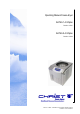
Operating Manual Freeze-dryer ALPHA 1-4 LDplus Part. No. 101541 ALPHA 2-4 LDplus Part. No. 101542 Version 11.2006 –Translation of the original operating manual Revision 1.
Operating Manual ALPHA 1-4 LDplus ALPHA 2-4 LDplus Order Number: Serial Number: In case of inquiries please state the above numbers. Copyright by Martin Christ Gefriertrocknungsanlagen GmbH An der Unteren Söse 50 37520 Osterode am Harz Germany Phone +49 (0) 55 22 / 50 07-0 Fax +49 (0) 55 22 / 50 07-12 E-mail: info@martinchrist.de Internet: www.martinchrist.de For service: please use our service request form on our website: www.martinchrist.
Contents 1. General Information 1.1. 1.2. 1.3. 1.4. 1.5. 1.6. 1.7. 2. 15 General Information on Freeze-drying........................................................ 15 Preparation................................................................................................ 18 Freezing .................................................................................................... 18 Main Drying ...............................................................................................
5. LDplus Control System 5.1. 5.2. 5.3. 5.4. 5.5. 5.6. 5.7. 5.8. 5.9. 6. 7. 7.2. 7.3. Contents 53 Power Failure ............................................................................................ 53 Insufficient Vacuum ................................................................................... 53 Unit does not function ................................................................................ 54 Insufficient Ice Condenser Temperature..........................................
8. Options 8.1. 8.2. 8.3. 8.4. 8.5. 9. 63 Process Control System LPC-32, Software ................................................ 63 Process Control System LPC-32, Software with PC hardware .................... 63 LyoLog LL-1 (Documentation Software) ..................................................... 63 LDplus Simulation Tool (Training Software) ............................................... 63 Electrical lifting device ...............................................................................
1. General Information 1.1. Introduction What is freeze-drying (Lyophilisation)? Freeze-drying means: Extraction of water from frozen material. The drying process takes place by avoiding the liquid state through sublimation, i. e. direct conversion from ice to vapour. This happens under vacuum and the temperature in the product is normally less than -10°C.
1.2. Applications The freeze-dryer ALPHA 1-4 LDplus / ALPHA 2-4 LDplus is a highperformance universal laboratory and pre-production unit for freezedrying of solid or liquid products in ampoules, vials, glass flasks, plasma bottles or dishes.
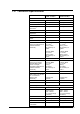
1.3. Technical Specification ALPHA 1-4 LDplus ALPHA 2-4 LDplus Performance data Ice condenser capacity max. 4kg max. 4kg Ice condenser performance1) max. 4kg/24h max. 4kg/24h Ice condenser temperature1) approx. –55°C approx. –85°C Ice condenser chamber volume: approx. 6,5l approx. 6,5l Max. shelf surface area when drying outside the ice condenser chamber (process B): 5 shelves, Ø265 Atotal 0.28m2 spacing: 79mm with accessory no. 120902 or 5 shelves, Ø360 Atotal 0.
ALPHA 1-4 LDplus Electromagnetic compatibility according to EN 55011: ALPHA 2-4 LDplus class B class B see label on the back of the unit see label on the back of the unit Filling quantities: Refrigerant: Connection requirements with vacuum pump 0.4KVA: Electrical connection: 1 x 230V / 50-60 Hz (others upon request) 1 x 230V / 50-60 Hz (others upon request) Power consumption: 1,3kVA 2kVA Max.
1.4. Scope of delivery The scope of delivery includes: 1 tube of high-vacuum grease 1 litre vacuum pump oil (only in case a pump is delivered) 0.5 m drain hose (silicone 9 x 12 mm) 1 operating manual and further detailed technical documentation The scope of delivery does not include: Commissioning of the unit (inside Germany) can be performed upon request and will be invoiced at cost. Installation of the exhaust pipe of the vacuum pump (not necessary when using an exhaust filter). 1.5.
1.6.3. ADVICE! Cleaning and Maintenance of the Unit! For infectious, toxic, pathogenic and radioactive substances the corresponding safety regulations must be observed. 1.6.4. WARNING! Freezing of Limbs to Surfaces! During operation of the freeze-dryer dangerous situations in the ice condenser chamber may arise. When putting in the shelves take care that limbs do not come into contact with the condenser in the ice condenser chamber as the limbs may become frozen to the surface.
1.7. Prohibited Freeze-drying Processes 1. Operation of freeze-dryer when not installed correctly. 2. Operation of freeze-dryer without panels. 3. Operation of freeze-dryer by non-authorised personnel. 4. Operation of freeze-dryer with shelves not installed properly. 5. Operation of freeze-dryer with very corrosive substances (e.g. hydrogen chloride). It is not allowed to dry these substances, at least special safety measures have to be observed.
2. General Information on Freeze-drying 2.1. General Information on Freeze-drying Freeze-drying is the most gentle process for drying products. It is based on the physical phenomenon of sublimation i.e. the direct conversion from solid to gaseous state. The frozen product is placed in the vacuum drying chamber for drying. The ice condenser can also be described as a vapour pump as the moisture which evaporates under vacuum during drying freezes onto the ice condenser.
Sublimation The principle of sublimation is briefly explained using the phase diagram of water (freeze-drying of mainly aqueous solutions, see vapour pressure curve). If the atmospheric pressure is higher than 6.11 mbar, water passes through all three phases (solid, liquid, gas) when the temperature is lowered or raised. At 6.11 mbar the melting pressure curve, vapour pressure curve and sublimation pressure curve meet in one point called triple point.
°C °C mbar mbar °C °C mbar mbar 0 6,110 -20 1,030 -40 0,120 -60 0,011 -1 5,620 -21 0,940 -41 0,110 -61 0,009 -2 5,170 -22 0,850 -42 0,100 -62 0,008 -3 4,760 -23 0,770 -43 0,090 -63 0,007 -4 4,370 -24 0,700 -44 0,080 -64 0,006 -5 4,020 -25 0,630 -45 0,070 -65 0,0054 -6 3,690 -26 0,570 -46 0,060 -66 0,0047 -7 3,380 -27 0,520 -47 0,055 -67 0,0041 -8 3,010 -28 0,470 -48 0,050 -68 0,0035 -9 2,840 -29 0,420 -49 0,045 -69 0,0030
2.2. Preparation In case the unit is equipped with a pressure control valve the vacuum pump should be warmed up. The operation temperature should be reached before loading the vacuum pump with condensable gases. In this way, the service life of the vacuum pump can be considerably extended. The vacuum pump can be operated already during the freezing process when the pressure control valve is closed.
Possible water residue must be removed from the ice condenser chamber. The drain valve is closed. The ground-in stopper of the drying chamber must be greased with high-vacuum grease! The layer thickness of the product should not exceed 1 to 2 cm as otherwise this has a negative effect on the duration of the drying process. 2.4. Main Drying The vacuum pump is switched on. Please note: Defrosting during the drying process is possible (visible foaming) when drying products containing e. g.
With increasing pressure (not vacuum!) the rate of sublimation rises and the drying period is shortened. The water vapour generated during the main drying phase is not pumped off by the vacuum pump but collected by the ice condenser. The purpose of the vacuum pump is to lower the partial pressure of the non-condensable gases so that the water vapour can be transported from the product to the ice condenser.
The drying time depends heavily on the drying vacuum. The nearer the vacuum is to the solidification point in accordance with the vapour pressure curve above ice, the shorter the drying time is. Interesting correlations : 1.0 gram of ice at 1.0 mbar assumes a volume of 1 m³ vapour 0.1 mbar assumes a volume of 10 m³ vapour 0.
2.5. Final Drying The final pressure in the drying chamber depends on the ice condenser temperature according to the vapour pressure curve above ice : e. g. 1.030 mbar correspond to -20°C 0.370 mbar correspond to -30°C 0.120 mbar correspond to -40°C 0.040 mbar correspond to -50°C 0.011 mbar correspond to -60°C The unit is in operating condition if the temperature of the ice condenser is lower than -50°C and the pressure is lower than 0.120 mbar.
Pipe connection for vacuum pump (behind baffle plate) Operating Manual Freeze Dryer ALPHA 1-4 LDplus / ALPHA 2-4 LDplus General Information on Freeze-drying 23
3. Description of the Freezedrying Processes 3.1. Separate Freezing and Drying Outside the Ice Condenser Chamber (Process B) on Shelves It is also possible to dry the product outside the ice condenser chamber. In this case, the product has to be frozen e.g. in a deepfreeze. Possible water residue is removed from the ice condenser chamber. The drain valve is opened so that the water residue can drain off. The ice condenser chamber should be wiped out if necessary.
3.2. Separate Freezing and Drying Outside the Ice Condenser Chamber (Process B) with Sealing Device Possible water residue is removed from the ice condenser chamber. The drain valve is opened so that the water residue can drain off. The ice condenser chamber should be wiped out if necessary. The refrigeration compressor and the vacuum pump are activated via the control system to start the pre-freezing of the ice condenser and the warming-up of the vacuum pump.
3.3. Separate Freezing and Drying of Liquids in Flasks (Process B) Possible water residue is removed from the ice condenser chamber. The drain valve is opened so that the water residue can drain off. The ice condenser chamber should be wiped out if necessary. The refrigeration compressor and the vacuum pump are activated via the control system to start the pre-freezing of the ice condenser and the warming-up of the vacuum pump. The valve is closed during warming-up of the pump.
3.4. Separate Freezing and Drying of Liquids in Ampoules (Process B) The refrigeration compressor and the vacuum pump are activated via the control system to start the pre-freezing of the ice condenser and the warming-up of the vacuum pump. The valve is closed during warming-up of the pump. In case the unit is not equipped with an electromagnetic pressure control valve we recommend to use a manual stop valve. Without such a valve the vacuum pump must not be warmed up.
4. Installation and Commissioning of the Unit 4.1. Site of Installation WARNING! Papers, cloths or similar items must not be put behind the unit as the air circulation of the heat exchanger will not work any more. The freeze-dryer should be horizontally aligned. The ambient temperature should be within approx. +10°C and +25°C. The refrigeration compressor of the freeze-dryer is air-cooled. Sufficient air circulation must be ensured. A distance of at least 30 cm to the wall should be kept.
4.4. Checking the Earth Connection For checking the earth connection there is a screw for equalising the ground potential on the rear panel of the freeze-dryer. The check can be carried out by means of an appropriate measuring device. 4.5. Aeration The aeration and drain valve at the lower left side of the unit is used to vent the ice condenser chamber.
4.7. Vacuum Pump Exhaust The oil mist which is produced during opferation of the vaccum pump must be removed. A ½" hose can be connected to the exhaust flange of the vacuum pump RZ-2 or RC-5 and a ¾" hose is connected to the exhaust flange of the vacuum pump DUO 5 or DUO 10. The hose either leads into the open air or into a vent. During installation of the pipe care must be taken that condensate cannot flow back into the pump.
4.8.1. Functional Components and Control Elements Aeration and drain valve Ice condenser chamber Ice condenser LDplus control system Mains switch Vacuum connection Additional connection interface (option, sep.
4.8.2. Connection of vacuum sensor vacuum Pump, and pressure control valve Connection diagram Fig.1 Process A (single-chamber system): Freezing and gentle drying of low-freezing and thermolabile substances on cooled shelves inside the ice condenser chamber (see figure 1). Typical drying vessels:: Dishes Injection vials (can be sealed under vacuum) Fig. 2 Process B (double-chamber system): Separate freezing (e.g.
The accessory components are connected to the ALPHA 1-4 / 2-4 LDplus freeze-dryer according to the connection diagram. Please observe the following: Centring rings and clamping flanges with wing nuts are used as connecting elements (small-flange connection according to ISO 28403 or DIN 2861, see the following instructions).
Installation of the VSP62/63 vacuum sensor The vacuum sensor has to be connected to the vacuum connection at the back of the unit in an upright position using a centring ring and a clamping ring. The sensor connecting cable has to be connected to the corresponding socket at the back of the unit. After power-on, the vacuum sensor needs a few minutes to reach its operating temperature.
4.8.3. Diagram of the accessories The other accessories (e.g. drying chamber, shelves, and connections for round bottom flasks) will be completed according to the scope of supply. Drying chamber Ø300 with 12 connections Ground-in stopper Rubber valve Distributor , Drying vessel e.g. ampoule Dying vessel e.g. round bottom flask 3 or 5 shelves Ø265, unheated Drying vessel e.g.
Rubber valve Drying vessel e.g. wide-neck filter bottle Drying vessel e.g. injection bottle Manifold, various types, for a max. of 24 rubber valves Dying vessel e.g.
Drying chamber Rubber valve Connection piece for rubber valve to extend the drying chamber, a max. of 18 pieces Dying vessel e.g. round bottom flask Distributor Drying vessel e.g. ampoule Max. 5 shelves Ø375 (unheated) Drying vessel e.g.
4.8.4. Rubber valves The rubber valves (part no. 121860) enable the connection of round-bottom flasks, wide-neck filter bottles, or distributors for ampoules to a manifold or drying chamber. Depending on the connector of the components, the blue plug can be removed. 1 1 Locking bolt 2 Connection to freezedryer (e.g. via a manifold) 3 Aeration connection 4 Vessel connection 5 Rubber plug 2 3 4 5 NOTE! The rubber valves come supplied in an ungreased state.
In position (3), the aeration connector and the vessel connector are closed. 4.8.5. Switching-on Press the mains switch on the right side of the unit to switch the unit on. The initialization of the LDplus control system starts. This may last for several seconds. When the unit is switched on for the first time (after delivery from the factory), the user will be guided through the LDplus control system in the form of a tutorial for a quick familiarisation with the unit.
5. LDplus Control System 5.1. Introduction LDplus (Lyo Display Plus) stands for a convenient user interface for controlling freeze-drying processes. 5.2. LDplus control panel 1. 3. 2. 4. 1. 2. 3. 4. 5. 5. Illuminated LC display (240x64 pixels) Left softkey Right softkey “Up” key “Down” key 5.3. Brief Guide - Handling The LDplus control system is operated via four keys that are located centrally on the touch-sensitive control panel.
5.4. Visual components of the LDplus control system The LC display is divided into the three following areas: 1. Main window 2. Status bar 3. Softkey function Main window Softkey function 5.4.1. Status bar Main window The main window shows set values and actual values, menus and process-relevant information. 5.4.2. Status bar The status bar shows the current operating mode, the active phase and other relevant information. The status bar is visible at all times.
5.4.2.2. Active phase Freezing The ice condenser is cooled. WarmUp VP The ice condenser is cooled and the vacuum pump is activated with the pressure control valve closed. If no pressure control valve is installed, the drying chamber has to be shut off from the vacuum pump using a manual valve, for example. Main drying The drying chamber is evacuated with the ice condenser being cooled. If a vacuum control system is included, the vacuum is controlled with the corresponding set value for main drying.
5.5. Values window The values window is displayed after the initialization of the LDplus control system. It is divided into two areas, the left-hand values window and the right-hand values window. The left-hand and right-hand value windows are structured as follows: Measuring channel Set value Unit of the measured value Actual value The “up” key is used to select the measuring channel to be displayed in the left-hand values window.
5.6. Mode The mode selection can be activated by pressing the left-hand softkey Mode in the active values window. The function Mode includes the operating mode selection and the phase selection. Freeze-drying comprises the following four phases: Freezing Warm-up vacuum pump Main drying Final drying 5.6.1. Starting a drying process If the unit is in standby mode, pressing the softkey Mode leads to an inquiry concerning the phase to be used for starting the freeze-drying process.
As an option, it is possible to change over to the next phase automatically when the preselected time is over. This applies only to a phase change from: Freezing Warm-up vacuum pump Main drying Final drying The option can be activated under Menu -> Options -> Settings -> Automatic phase change. 5.7. Main menu The main menu can be activated by pressing the right-hand softkey Menu in the active values window.
5.7.1.1. Set values for freezing Timer Time for the freezing phase section time. You can set a time between 1 minute and 200 hours. Selecting the infinite set value ( ) deactivates the timer for the freezing phase. 5.7.1.2. Set values for main drying & final drying Timer Time for the main or final drying phase section time. You can set a time between 1 minute and 200 hours. Selecting the infinite set value ( ) deactivates the timer for the main or final drying phase.
5.7.4. Options The Options menu includes the functions Contrast, Language, Settings and Service. 5.7.4.1. Contrast The Contrast menu is used to change the contrast of the LC display. The contrast has to be adapted to the local light conditions at the installation site of the freeze-dryer. 5.7.4.2. Language The LDplus control system can be used in the German, English, French, Spanish, Polish ior Russian language. 5.7.4.3.
Time Defrosting Input of the time that is required for defrosting the ice condenser. Temperature Defrosting Input of the maximum temperature of the chamber or ice condenser during the defrosting phase. 5.7.4.4. Service menu The settings of the service menu should only be modified by authorised persons in order to ensure the trouble-free operation of the freeze-dryer! LDplus configuration Configuration of accessories (options). If an option is installed, it has to be activated with “yes".
5.8. Process and equipment information system A detailed list of error messages can be found in the chapter "Error Correction". The process & equipment information window is displayed whenever the LDplus control system generates a new information message. In addition, the user can select Menu -> Process & Equipment Information System in the main menu to check whether messages are pending. If no messages are pending, the following window is displayed.
5.9. LDplus special functions 5.9.1. Defrosting the ice condenser Depending on the equipment variant, the freeze-dryer can be equipped with a defrosting device. If the system is defrosted with a defrosting device, heat is supplied to the ice condenser chamber in order to melt the ice that has built up on the ice condenser. Enter the required time for defrosting under Menu -> Options > Time Defrosting.
6. Error Correction 6.1. Power Failure The control system continues the process after a power failure. The preselected conditions remain saved during the process run. The process times, the total time and the section time are reset. In the event of a power failure during the drying process the batch may become unusable. Whether the batch can be saved depends on the drying phase in which the product was when the power failure occurred.
Check if the whole surface of the ground-in socket of the mountable drying chamber has been greased evenly and completely with vacuum grease. When using drying chambers with several connections for rubber valves the valves should be taken off and the connections should be sealed with rubber stoppers. To check the valves they are connected one after the other and tested under vacuum. Check the vacuum sensor for pollution such as water residue.
6.4. Insufficient Ice Condenser Temperature The refrigerator is equipped with a protection device against overpressure in the refrigerating system and with a thermal motor protection. The protection devices are released with too high ambient temperatures, with insufficient air circulation of the heat exchanger of the refrigerating system, with overload of the refrigerating system. The refrigerating system is switched off automatically.
Vacuum sensor defective This error message is displayed in case the unit control system reads in an invalid value supplied by the vacuum sensor. Check the connecting cable and the connections to the vacuum sensor, perform an atmospheric adjustment of the sensor or replace the vacuum sensor if necessary. Causes: Vacuum sensor not connected. Heating spiral of vacuum sensor broken. Overpressure refrigerator 1 Overpressure in refrigeration unit KM1, released via the pressure switch.
7. Maintenance and Service 7.1. Maintenance 7.1.1. Ice Condenser Chamber Before each start-up ensure that all water residue has been removed from the ice condenser chamber. If necessary, wipe the ice condenser chamber. Before every drying process it is recommended to open and close the drain valve once. 7.1.2. Heat Exchanger A laminated heat exchanger is used to cool the refrigerant compressed by the refrigerator. The heat exchanger is placed at the back of the unit.
7.1.4. Rubber Valves Special attention must be paid to the rubber valves. If the valves are stiff, they must be dismantled, cleaned, slightly greased with vacuum grease and reassembled. 7.1.5. Vacuum Pump For maintenance of the vacuum pump please refer to the separate operating manual. Additionally, we would like to emphasise the following points: The oil level of the vacuum pump must be regularly checked using the inspection glass (in case of continuous operation at least once a week).
a mark or any other change, as well as corrosion is detected, the part in question (shelf, vessel, drying chamber etc.) must be replaced immediately for safety reasons. Fans, lid seal, vessels, racks, drying chamber and shelves must be cleaned regularly in order to avoid damage. Cleaning of accessories should be carried out away from the freeze-dryer once a week or preferably after every use.
7.1.8. Disinfection of Drying Chamber, Lid and Accessories All usual disinfectants like e. g. INCIDUR, Melisiptol, Sagrotan, Buraton or Terralin (available at laboratory retail suppliers) can be used. NOTE! Check compatibility with lid and drying chamber; also see enclosure “Resistance to stress cracking and chemical influences PLEXIGLAS " (acrylic glass). The freeze-dryers and the accessories consist of different materials. A possible incompatibility must be considered.
7.2. Service DANGER! In the event of service work that requires the removal of the panels, there is a risk of electric shock or mechanical injury. Only qualified specialist personnel is authorised to perform this service work. The freeze-dryer is subject to high mechanical stress. In order to be able to withstand this high level of stress, high-quality components were used during the production of the freeze-dryer. Nevertheless, wear cannot be excluded and it may not be visible from the outside.
7.3. Return of defective parts Although we exercise great care during the production of our products, it may be necessary to return a unit or accessory to the manufacturer. In order to ensure the quick and economical processing of returns of freeze-dryers, rotational vacuum concentrators, spare parts, or accessories, we require complete and extensive information concerning the process.
8. Options 8.1. Process Control System LPC-32, Software Upon request. See separate operating manual. 8.2. Process Control System LPC-32, Software with PC hardware Upon request. See separate operating manual. 8.3. LyoLog LL-1 (Documentation Software) Upon request. See separate operating manual. 8.4. LDplus Simulation Tool (Training Software) Upon request. 8.5.
9.
Operating Manual Freeze Dryer ALPHA 1-4 LDplus / ALPHA 2-4 LDplus Enclosures 67
Operating Manual Freeze Dryer ALPHA 1-4 LDplus / ALPHA 2-4 LDplus Enclosures 69
Enclosures Operating Manual Freeze Dryer ALPHA 1-4 LDplus / ALPHA 2-4 LDplus
Operating Manual Freeze Dryer ALPHA 1-4 LDplus / ALPHA 2-4 LDplus Enclosures 71
Enclosures Operating Manual Freeze Dryer ALPHA 1-4 LDplus / ALPHA 2-4 LDplus
Operating Manual Freeze Dryer ALPHA 1-4 LDplus / ALPHA 2-4 LDplus Enclosures 73
Enclosures Operating Manual Freeze Dryer ALPHA 1-4 LDplus / ALPHA 2-4 LDplus
Operating Manual Freeze Dryer ALPHA 1-4 LDplus / ALPHA 2-4 LDplus Enclosures 75
Enclosures Operating Manual Freeze Dryer ALPHA 1-4 LDplus / ALPHA 2-4 LDplus
Operating Manual Freeze Dryer ALPHA 1-4 LDplus / ALPHA 2-4 LDplus Enclosures 77
Enclosures Operating Manual Freeze Dryer ALPHA 1-4 LDplus / ALPHA 2-4 LDplus
Operating Manual Freeze Dryer ALPHA 1-4 LDplus / ALPHA 2-4 LDplus Enclosures 79
Enclosures Operating Manual Freeze Dryer ALPHA 1-4 LDplus / ALPHA 2-4 LDplus
Operating Manual Freeze Dryer ALPHA 1-4 LDplus / ALPHA 2-4 LDplus Enclosures 81
Enclosures Operating Manual Freeze Dryer ALPHA 1-4 LDplus / ALPHA 2-4 LDplus
Operating Manual Freeze Dryer ALPHA 1-4 LDplus / ALPHA 2-4 LDplus Enclosures 83
Enclosures Operating Manual Freeze Dryer ALPHA 1-4 LDplus / ALPHA 2-4 LDplus
Operating Manual Freeze Dryer ALPHA 1-4 LDplus / ALPHA 2-4 LDplus Enclosures 85