
Instruction Manual


Rotational Vacuum Concentrator RVC 2-33 IR
5 Set-up and connection
26
Version 08/2009, Rev. 2.1 of 02/12/2014 • sb
Translation of the original operating manual
Pos: 86 / 200 Chris t/ 370 R VC-B A (S TANDA RDM OD ULE)/ 050 A u fstell ung u nd Ans chl uss/ 050 A ufst ell ung un d A nschl uss ==== == ===== == ===== == ==== == @ 25\ mod _14 049 850 8287 8_6 8.d ocx @ 186 981 @ 1 @ 1
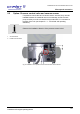
5 Set-up and connection
Pos: 87 / 200 Chri st /37 0 RVC -BA (STAN DAR DM ODULE )/ 050 Au fs tellu ng u nd Ans c hluss/ 050 -00 10 A ufs tello rt, E ins atzo rt @ 25\ mod _14 0498 508 370 7_6 8.do cx @ 1 869 95 @ 2 @ 1
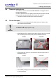
5.1 Installation site
Operate the RVC only in closed and dry rooms.
• The table must be stable and have a solid, even tabletop.
• Ensure sufficient ventilation. Do not place any paper, cloth, or similar
material behind or under the unit, since otherwise the air circulation will
be impaired.
• Keep a safety distance of at least 30 cm from the wall so that the vents
in the unit remain fully effective.
• The ambient temperature must be in the range of +10°C to +25°C.
• Do not subject the RVC to thermal stress, e.g. by positioning it near
heat generators.
• Avoid direct sunlight (UV radiation).
Pos: 88 / 010 Uni ve rsalm odul e/Leerz eil e @ 0\mo d_1 202116 244 500 _0.doc x @ 114 @ @ 1
Pos: 89 / 200 Chris t /37 0 RVC -BA (STAN DAR DM ODULE )/ 050 Au fst ellu ng u nd Ans c hluss/ 050 -00 20 E ner gieve rsor gun g-- -- ----- --- ----- ----- --- ----- --- ----- - @ 25\ mod _140498 508 458 5_6 8.doc x @ 1 870 09 @ 2 @ 1
5.2 Power supply
Pos: 90 / 200 Chri st /37 1 RV C-BA (PRO JEK TE) /RV C 2-3 3 IR/ 050 A u fstell u ng und A ns chlus s/ 050 -00 20-001 0 A nsc hlus sa rt RVC 2 -33 IR @ 31\ mod_140 748 406 576 8_6 8.doc x @ 2090 14 @ 3 @ 1
5.2.1 Connection
DANGER
The operating voltage on the name plate must correspond to the local
supply voltage!
CHRIST rotational vacuum concentrators are units of safety class I.Units of
the type RVC 2-33 IR have a three-wire power cord with an IEC C13
connector (see chapter 10 - "Technical data").
An equipotential bonding screw is located on the back (see chapter 2.1.1 -
"Functional and operating elements"). This equipotential bonding screw can
be used to perform an earth conductor check.
Pos: 91 / 010 Uni ve rsalm odul e/Leerz eil e @ 0\mo d_1 202116 244 500 _0.doc x @ 114 @ @ 1
Pos: 92 / 200 Chri st /37 0 RVC -BA (STAN DAR DM ODULE )/ 050 Au fs tellu ng u nd Ans c hluss/ 050 -00 20- 002 0 Sic heru nge n ba usei ts @ 25 \mo d_1404 9850 854 66_ 68.d ocx @ 187 023 @ 3 @ 1
5.2.2 Customer-provided fuses
Typically, the RVC must be protected with 16 Amp G fuses that are to be
provided by the customer.
Pos: 93 / 010 U nive rsalm odul e/S eite nwechs el @ 0 \mo d_1 202116 244 312_ 0.d ocx @ 105 @ @ 1