36" and 42" WOOD BURNING FIREPLACES INSTALLATION AND OPERATING INSTRUCTIONS Glass Doors, Fan Assembly, and Outside Combustion Air Kit Available MODELS: 400BWBA 400BWBIA 400BWBCA 400BWBCIA 500BWBA 500BWBIA 500BWBCA 500BWBCIA 400BWBA and 500BWBA Series Radiant Type 400BWBCA and 500BWBCA Series Circulating Type These fireplaces are U. L.® listed for use with “S” Series chimney system components. Only Unvented Gas Log Sets which have been found to comply with the Standard For Unvented Room Heaters ANSI Z21.
CONTENTS CONGRATULATIONS! You have chosen the finest wood burning fireplace available. Your fireplace has been designed for years of heating and viewing enjoyment. Please take time to read this entire manual before installing or operating your fireplace. Listing and Code Approval .............................................. 2 Important Safety Information .......................................... 3 Operation Guidelines .......................................................
IMPORTANT SAFETY INFORMATION • Read these instructions entirely before beginning any part of the installation. Save these instructions for any future repairs. • Use these instructions as a guide during the installation of the fireplace. • Install all the parts used with this fireplace system in accordance with these installation instructions. Failure to do so may be hazardous and will void the warranty. • Do not alter fireplace and accessories in any way that is not specifically recommended in this manual.
OPERATION GUIDELINES HOW YOUR FIREPLACE SHOULD BE USED This fireplace is intended for supplemental heating only and is not intended for use as a primary heating system. This fireplace is designed to sit directly on a combustible floor. The fireplace must be installed with clearances to combustible building materials as specified by this manual.
OPERATIONAL GUIDELINES FLUE DAMPER CHIMNEYS The fireplace also is equipped with a flue damper which must be open when the fireplace is in use. The flue damper control lever is located inside the fireplace. The counterweighted damper is operated by simply unlocking up to open or pulling and locking down to close the damper. When the fireplace is not in use, the damper should be closed to prevent cold air form entering the chimney as well as preventing warm air in the room from escaping up the chimney.
PRODUCT FEATURES PRODUCT SPECIFICATIONS • This fireplace is designed to burn solid wood fuel (wood), UL-classified processed solid fuel fire logs, or a certified decorative gas appliance may be installed in the fireplace as described later by this instruction manual. • The appliance must be properly connected to a venting system.
Plan for the installation of your fireplace. This includes determining where the unit is to be installed, the vent configuration to be used, framing and finishing details, and whether any optional accessories (i.e. blower, wall switch, or remote control) are desired. Consult your local building code agency to ensure compliance with local codes, including permits and inspections. CAUTION FIREPLACE LOCATION Do not install fireplace over carpeting.
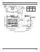
FIREPLACE DIMENSIONS Outside Connector Center Line A 71/2" 131/2" 10" TOP VIEW 213/4" Framing Dimension 21" A B C 400 Units 500 Units 243/4" 36" 401/2" 303/4" 42" 461/2" /2" or 5/8" Drywall Spacers 1 /2" or 5/8" Drywall Spacers 1 6 /2" 1 403/4" 343/8" 400BWBA 400BWBIA 500BWBA 500BWBIA 400BWBCA 400BWBCIA 500BWBCA 500BWBCIA Framing Dimension 211/2" 95/8" Air Kit 171/4" 61/2" 7" 25/8" 87/8" B C Gas 133/4" Framing Dimension FRONT VIEW Electrical SIDE VIEW Figure 3 - Fireplace Dime
INSTALLATION PREPARATION LOCATING CHIMNEY • Survey the planned location for the fireplace for overhead plumbing or electrical wires, etc. This could make installation harder. It could also be a hazard for persons installing or cleaning the chimney. • Do not install where the chimney cap will be near abrupt changes in the roof shape, nearby wall or embankments, under or near trees or above the roof of a single story wing of a two story building. See Figure 4.
INSTALLATION PREPARATION LOCATING CHIMNEY (CONTINUED) • If the fireplace is to be installed on an outside wall, the surrounding walls (chase) must be constructed and insulated. See Figure 5. If you do not insulate the fireplace from outside temperatures, heat loss through and around the fireplace will occur.
FLOOR PROTECTION INSTALLING FIREPLACE ON COMBUSTIBLE FLOOR If fireplace is installed on a combustible floor, protect the floor area either side of the fireplace opening and in the front with an insulating non-combustible hearth extension. (16" [400 unit] or 20" [500 unit] minimum in front of fireplace and 8" minimum on both sides. See Figures 6 through 12. 8" Min. Fireplace Hearth Extension Clearances & Width 400 Unit 500 Unit 16" Min. (400 Unit) 6" Min. Brick 20" Min.
FLOOR PROTECTION INSTALLING FIREPLACE ON COMBUSTIBLE FLOOR (CONTINUED) This hearth extension must be either 6" (minimum) thick stone or brick; a H1652 (400 units) or H2066 (500 units) Hearth Extension Kit; or a locally constructed hearth that has a “K” factor less than .43 and at least ½" thick. For other non-combustibles, the total thickness minimum is 1.16 times its thermal conductivity (K).
FIREPLACE INSTALLATION UNPACKING FIREPLACE Unpack and check the fireplace and chimney for damage. If any items are been damaged or missing, contact your Martin Hearth and Heating dealer. Do not substitute parts. Use only parts listed for use with Martin Hearth and Heating Models 400BWBA, 400BWBIA, 400BWBCA, 400BWBCIA. 500BWBA, 500BWBIA, 500BWBCA and 500BWBCIA fireplaces. CLEARANCES 1. Provide required clearances shown in Figures 10 through 12. Provide 2" minimum chimney air space clearance to combustibles.
FIREPLACE INSTALLATION CLEARANCES CONTINUED Flue Outlet Height Round Chimney Cap Model SC 20' min. Height (4-30 Elbows) 86' max. Height (Chimney Support Every 30') Roof Flashing Model 612 Storm Collar Firestop - Model SF (Requires 15"x15" Opening) 2" min. Air Space to Combustibles Chimney (2" min.
CHIMNEY INSTALLATION INSTALLING CHIMNEY SAFETY INFORMATION WARNING You must properly install the chimney to assure safe and satisfactory performance of the fireplace. This is an important part of the installation. Review the Chimney Installation Section thoroughly. For your safety, some of the important things to remember in regard to chimneys are listed below: • Use only parts and accessories labeled for use with this fireplace. • Use only undamaged parts and accessories.
CHIMNEY INSTALLATION INSTALLING CHIMNEY SAFETY INFORMATION (CONTINUED) SC Chimney Cap Storm Collar Flashing (612 or 1212) Flue Outlet Height Model SC Chimney Cap 3' Min. and 2' Above Any Point Within 10' Storm Collar (Including with Cap) Attic Space Attic Space See Table 1 for Roof Opening Size SF Firestop Spacer (2" Air Space Clearance to Combustibles) 15" Square Hole in Joist (2" Air Space Clearance To Combustibles) 15" Square Opening in Joist 2" Min. Clearance to Combustibles 3' Min.
CHIMNEY INSTALLATION LOCATING CENTER LINE Center Line to Chimney You will need to lay out, cut and frame openings through all ceilings and the roof at the point where the chimney will pass through. Place fireplace in planned position for installation. Unless the chimney is to be offset, the point where the center line of the chimney will pass through the ceiling and roof can be determined with a plumb line. See Figure 16. Drive a nail in the center point.
CHIIMNEY INSTALLATION INSTALLING “S” SERIES CHIMNEY SPACERS To install the “S” series chimney sections, insert the male end of the flue (the smallest diameter pipe) into the flue outlet of the fireplace. Press down until the snap locks engage. Continue to add chimney sections on top of each other until chimney is at least 6" above roof opening on all sides. See Figure 19. Note: As the chimney sections are installed, check each joint to make sure it is properly locked to the previous section.
CHIIMNEY INSTALLATION INSTALLING CHIMNEY SUPPORTS Note: Outer Pipe For a total fireplace installation of more that 30' feet, you must use chimney support model SCS at or below 30' to support the weight of additional chimney pipe. To install the chimney support, place the crimped end of the flue and outlet air duct portions into the last section of chimney pipe. Push down until the outside of inlet air duct of the chimney support overlaps and snap locks the chimney support into the chimney section.
CHIIMNEY INSTALLATION Center Line Storm Collar Flashing Roof Continue Chimney to Proper Height and Install Round Chimney Cap or Chimney Housing Center Line Support Straps Note: Do not let support straps penetrate firestop Note: Chimney must be enclosed in accessible areas Vertical Chimney Enclosure Support Straps SF Firestop Spacer 2" min. Air Space Clearance to Combustibles Note: Two (2) elbows may be used when total installation height is more than 13'.
CHIIMNEY INSTALLATION OFFSET INSTALLATION SEQUENCE Determine the location and amount of offset required. Select the combinations of chimney sections and elbows required from the Chimney Height and Offset Charts.
CHIIMNEY INSTALLATION OFFSET INSTALLATION SEQUENCE (CONTINUED) 1. Install the first SE30 elbow by placing the extended flue into the mating part of the fireplace or chimney section. Push down until the outside of inlet air duct of the elbow overlaps. Snap lock the elbow into the fireplace or chimney section. 2. Nail the support straps to the framing member with a minimum of two (2) 8-penny nails per strap. 3.
CHIIMNEY INSTALLATION CAUTION CHIMNEY CAP INSTALLATION (CONTINUED) Flashing Cut Off 1/4" below Scribed Line Be careful to avoid electrical shock hazard when contacting wires to the metal chimney components. 1. Extend the regular chimney sections until the top of the chimney is 4" below the total flue height desired. Do not snap the last section of inlet air duct or largest diameter pipe in place until Step 3 is completed. 2.
CHIIMNEY INSTALLATION CHIMNEY CAP CHASE INSTALLATION WARNING The preinstalled chimney sections must be no more than 10" below the top of the chase. Plan the installation so that either a 2' or 3' chimney section will be used for the top section. This is necessary to completely install inlet air telescope and chimney cap into the top section. Be careful around electrical wires to avoid the electrical shock hazard of contacting the wires with the metal chimney components.
OUTSIDE COMBUSTION AIR PRECAUTIONS AND RECOMMENDATIONS COMBUSTION AIR 1. Locate combustion air assembly at an exterior location which is not likely to be accidentally blocked in any manner. Locate assembly above the snow line to prevent blockage by snow accumulation. 2. Never mount the combustion air inlet assemblyin a garage or storage area where combustible fumes such as gasoline might be drawn into the fireplace. 3.
OUTSIDE COMBUSTION AIR PRECAUTIONS AND RECOMMENDATIONS COMBUSTION AIR (CONTINUED) Firestop Spacer CAUTION Second Floor Duct Extended to Miss Joist Do not take combustion air from attic space or garage.
OUTSIDE COMBUSTION AIR PRECAUTIONS AND RECOMMENDATIONS MODEL AK-4 COMBUSTION AIR ASSEMBLY 1. Remove the cover plate from the 4" outlet opening location on the left or right outside of the fireplace. 2. Place the insulation ring between the AK-4 starting collar and fireplace wall. WARNING The use of outside air for combustion is optional unless required by building codes. It is only necessary to supply outside combustion air to one side of the fireplace. Use the model AK4 combustion air kit.
OUTSIDE COMBUSTION AIR PRECAUTIONS AND RECOMMENDATIONS MODEL AK-4 COMBUSTION AIR ASSEMBLY (CONTINUED) 7. If the duct is the insulated type, push the insulation back from one end of the duct approximately 2". See Figure 35. 8. Slip the exposed end of the duct over the starting collar on the fireplace. Approximately 2" Duct Connector 9. Using the sheet metal screws provided, secure the duct end to the collar attached to the fireplace. 10. Nail or screw the combustion air assembly to the surface of the wall.
If an unvented gas appliance is installed in the fireplace, the gas appliance must only be operated with the fireplace glass door fully open (if included). Only unvented gas log sets which have been found to comply with the standard for unvented room heaters, ANSI/IAS/AGA Z21.11.2 are to be installed in this fireplace. WARNING CAUTION GAS APPLIANCE INSTALLATION Do not operate an unvented gas log set in this fireplace with the chimney removed. 2.
INSTALLING GAS APPLIANCE PASSING GAS LINE THROUGH FIREPLACE WALL 1. Locate recessed area in side brick side liner. 2. Lightly tap recessed area with a hammer until a round hole is tapped out. See Figure 37. Back Brick Liner Side Brick Liner 3. Remove the two (2) screws that hold cover plates on jacket wrap. Discard cover plate. Hole 4. Install the gas pipe through the tube between the firebox and jacket. 5. Attach the gas appliance to the gas pipe according to the appliance makers instructions.
TRIM AND MANTEL INSTALLATION FOR GAS APPLIANCES Mantel Trim Installation (Unvented Gas Appliances Only) 1. Install hood on fireplace with mantels 12" from the opening of fireplace. Mantel may be no more than 12" deep. Combustible framing members may be placed across top spacers. See Figure 38. 2. Combustible mantel and/or trim may be installed within shaded area in Figure 39. Use only noncombustible materials below top of spacers and behind front face. Note: No combustible materials within 12" of opening.
TRIM AND MANTEL INSTALLATION FOR WOOD BURNING FIREPLACES The fireplace face may be left exposed or trimmed. If trim is installed, fasten it securely to face of fireplace. Seal any cracks between trim material and face of fireplace. Cracks can cause a fire and prevent fireplace from working properly. • Place wall ties in mortar joints of masonry trim. Fasten wall ties to face of fireplace with sheet metal screws. • Use only non-combustible materials below top of spacers.
GLASS DOOR INSTALLATION This fireplace has been tested and listed for use with optional Model GD36BA, BD36PBA, GD36SSA, GD42BA, BD42PBA, and GD42SSA glass doors. For installation of glass doors, see the instructions provided with the doors. FAN ACCESSORY The model 400BWBCA, 400BWBCIA, 500BWBCA, and 500BWBCIA fireplaces may be equipped with a Model FA2A fan accessory.
HOW TO BUILD A BETTER FIRE Fireplace damper must be fully opened when using a gas appliance. See Gas Appliance Installation for more guidelines. ADVANTAGES OF A WOOD BURNING FIREPLACE These are practical and ecological advantages of using wood as a fuel. Also to be considered is the aesthetic appeal. Most of us consider a wood fire with nostalgia. We enjoy the aroma and find the flickering light of a cozy hearth reminding us of things past. Wood has a low ash content.
FIREPLACE OPERATION WOOD VS. FOSSIL FUELS A FEW WORDS OF CAUTION Compared to fossil fuels, a full cord of dry hickory weighs about two tons and is approximately equal in heating value to a ton of hard coal. On a per pound basis, heavy hardwoods have about half the heating value of coal. The table below shows the relative densities and heat values of a variety of dry woods. Varieties at the top of the list (Dogwood) burn longer and those near the bottom (White Pine) ignite and burn quicker.
MAINTENANCE FUEL STORAGE Wood can be dried sufficiently for burning within a few weeks if protected form rain in a low humidity area. It is better to cut wood and allow it to dry for a year. In all cases, the wood should be stacked so that both ends of the sticks are exposed to the air and protected from rain. The drier the wood, the more usable heat produced by the fire and less likely rapid accumulation of soot and creosote within the chimney is to occur.
MAINTENANCE AND SAFETY CHECKLIST OF DO’S AND DON’Ts DO’S 1. Do check with local building officials to be sure the installation of the fireplace complies with all building codes and requirements. Obtain required building permits. Do plan your installation with safety as you primary consideration. 11. Do keep all flammable liquids, gases and pressurized containers away form the fireplace. 2. Do use only the prescribed material and parts for the installation of the fireplace. 13.
MAINTENANCE AND SAFETY DON’Ts 1. Donʼt allow other installations or operation considerations to take priority over safety considerations. 2. Donʼt attempt to use the fireplace until the installation is complete. 3. Donʼt use unlisted parts and accessories with the fireplace except for special flashings fabricated locally. 15. Donʼt dry clothing or other articles near the fireplace. 16. Donʼt store or place flammable liquids, gases or pressurized containers near the fireplace. 17.
REPLACEMENT PARTS REPLACEMENT PARTS ARE AVAILABLE THROUGH YOUR RETAILER Item Description 1 2 3 4 5 6 Weldment Air Door Rod Firescreen Panels Back Firebrick Assembly Side Firebrick Assembly Painted Grate Assembly Bottom Firebrick Assembly QTY 400 Unit 500 Unit 1 2 1 2 1 1 031867 61D0001 61D0102 61D0101 61D0020 61D0100 031867 61D0003 61D0107 61D0101 61D0022 61D0106 1 1 2 2 4 4 3 3 5 5 6 WARNING Circulating Models: 400BWBCA 400BWBCIA 500BWBCA 500BWBCIA 61D0008 6 Radiant Models: 400BWBA 4
REPLACEMENT PARTS ARE AVAILABLE THROUGH YOUR RETAILER REPLACEMENT PARTS Item Part No. Description 1 GD36PBA Optional 36" polished brass bifold glass door kit; polished brass finish frame; tempered clear glass 1 GD36BA Optional 36" black bifold glass door kit.
REPLACEMENT PARTS REPLACEMENT PARTS ARE AVAILABLE THROUGH YOUR RETAILER 1 4 3 2 7 5 6 13 11 8 9 12 10 14 REPLACEMENT PARTS (NOT SHOWN) Item SCL SQ8 SF30 S8 LFSQT SPC H36 VFK 61D0008 Description Round chimney cap with telescoping pipe and storm collar.
NOTES 42 61D0008
ATTENTION APPLIANCE INSTALLER PLEASE RETURN THESE OPERATING AND INSTALLATION INSTRUCTIONS TO THE CONSUMER! 61D0008 43
LIMITED WARRANTY FACTORY-BUILT FIREPLACE AND COMPONENTS (EXCEPT BLOWERS) WHAT IS COVERED AND FOR HOW LONG • Five-Year Coverage: For five years from the date this fireplace and components are first purchased for use, Martin Hearth and Heating will, at its option, repair or replace any defective part of this fireplace or components, or refund to you a sum not to exceed the factory retail price in effect at the time of purchase.