
User manual


Setup 7
INSTALLING A PLUG ON THE POWER CABLE
The power cable must be fitted with a grounding-type cord cap that fits your power distribution system.
Consult an electrician if you have any doubts about proper installation.
• Following the cord cap manufacturer’s instructions, connect the yellow and green wire to ground (earth), the
brown wire to live, and the blue wire to neutral. The table below shows some pin identification schemes.
APPLYING POWER
Warning! The power cables must be undamaged and
rated for the electrical requirements of all
connected devices.
Important! Powering through a dimmer system can
damage the fixture.
1 Verify that the supply cable is undamaged and rated
for the current requirements of all connected devices.
2 Plug the prepared power cable into the AC socket and
a grounded AC power supply.
Installation
LOCATION AND ORIENTATION
The CX-10 may be installed in any orientation. It can be fastened directly to a suitable surface, hung with a
rigging clamp, or placed directly on a level surface.
For safe operation, install the CX-10 in a location where
• the fixture is at least 0.1 meters (4 inches) away from combustible materials
• the fixture is protected from rain and moisture
• there is at least 0.1 meters (4 inches) clearance around the fan and control panel
• there are no flammable materials nearby
RIGGING OR MOUNTING THE CX-10
Warning! Block access below the work area before proceeding.
Warning! Always use a secure means of secondary attachment.
1 If using a rigging clamp (not included), verify that it is undamaged and can bear at least 10 times the fixture’s
weight. Bolt the clamp securely to the bracket with a grade 8.8 (minimum) M12 bolt and lock nut, or as
recommended by the clamp manufacturer, through the 13 mm hole in the center of the mounting bracket.
2 If fastening the fixture directly, verify that the hardware (not included) and mounting surface can bear at least
10 times the fixture’s weight. The four 6.2 mm holes and/or the 13 mm hole in the mounting bracket may be
used to fasten the fixtures.
3 Verify that the structure can support at least 10 times the weight of all installed fixtures, clamps, cables,
auxiliary equipment, etc.
4 Working from a stable platform, clamp or fasten the fixture to the structure.
Wire Pin Marking Screw color
brown live “L” yellow or brass
blue neutral “N” silver
yellow/green ground green
Table 1: Plug wiring
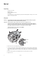
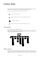
AC input & fuse holder
Data input
Data output