
User manual


8 CX-10
5 Install a safety cable that can hold at least 10 times the weight of the fixture through/over the support and
anywhere through the fixture’s aluminum frame.
6 Loosen the swivel locks and tilt the fixture to the desired angle. Turn the swivel locks clockwise to tighten.
When a handle reaches its limit, pull it out, turn counterclockwise, release, and continue tightening.
7 Verify that the fixture meets the location requirements listed previously.
Connecting the serial data link
The CX-10 has locking 3-pin data input and output sockets that are wired for use with DMX devices
with pin 1 to shield, pin 2 to cold (-) and pin 3 to hot (+). As some devices have 5-pin connectors, or 3-pin
connectors with reversed polarity on pins 2 and 3, the following adaptor cables may be required.
1 Connect the controller’s output to the fixture’s data
input. For a DMX controller with 5-pin output, use a
cable with a 5-pin male and a 3-pin female XLR
connector.
2 Connect the output of the fixture closest to the
controller to the input of the next fixture. If connecting a
fixture with pin 3 hot to a fixture with pin 3 cold, use a
phase-reversing adaptor.
3 To terminate the link, insert a male 120 Ω XLR
termination plug in the output of the last fixture.
TIPS FOR BUILDING A SERIAL LINK
• Use shielded twisted-pair cable designed for RS-485
devices: standard microphone cable cannot transmit DMX data reliably over long runs. For links up to 300
meters (1000 ft.) long, you can use 24 AWG, low capacitance, 85-150 ohm characteristic impedance,
shielded cable with 1 or more twisted pairs. For runs up to 500 meters (1640 ft.) use 22 AWG cable. Use an
amplifier if the serial link exceeds 500 meters.
• Never use a “Y” connector to split the link. To split the serial link into branches use a splitter such as the
Martin 4-Channel Opto-Isolated RS-485 Splitter/Amplifier.
• Do not overload the link. Up to 32 devices may be connected on a serial link.
• Terminate the link by installing a termination plug in the output socket of the last fixture on the link. The
termination plug, which is simply a male XLR connector with a 120 ohm, 0.25 watt resistor soldered
between pins 2 and 3, “soaks up” the control signal so it does not reflect back down the link and cause
interference. If a splitter is used, terminate each branch of the link.
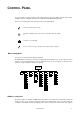
Phase-Reversing
Adaptor
Male Female
1
2
3
1
2
3
3-pin to 3-pin
P/N 11820006
Adaptor
Male Female
1
2
3
4
5
1
2
3
5-pin to 3-pin
P/N 11820005
Adaptor
Male Female
1
2
3
1
2
3
4
5
3-pin to 5-pin
P/N 11820004
Figure 1: Cable adaptors
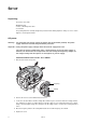
AC input & fuse holder
Data input
Data output