Atomic 3000 user manual TM
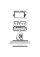
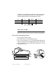
424 239 450 5 x Ø12.20 90 150 84 496 143 234 © 2001-2007 Martin Professional A/S, Denmark. Information subject to change without notice. Martin Professional A/S and all affiliated companies disclaim liability for any injury, damage, direct or indirect loss, consequential or economic loss or any other loss occasioned by the use of, inability to use or reliance on the information contained in this manual.
Contents Safety information . . . . . . . . . . . . . . . . . . . . . . . . . . . . . . . . . . .4 Preparation for use. . . . . . . . . . . . . . . . . . . . . . . . . . . . . . . . . . .6 Lamp . . . . . . . . . . . . . . . . . . . . . . . . . . . . . . . . . . . . . . . . . . . . . .9 Controller operation . . . . . . . . . . . . . . . . . . . . . . . . . . . . . . . . .11 Stand-alone operation . . . . . . . . . . . . . . . . . . . . . . . . . . . . . . .16 Remote controls . . . . . . . . . . . . . . . . .
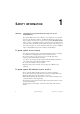
1 SAFETY INFORMATION Warning: This product is for professional use only! It is not for household use. The Atomic 3000 presents risks of lethal or severe injury due to fire and heat, electric shock, ultraviolet radiation, and falls. Flashing light is also known to trigger epileptic seizures in persons who are photosensitive. Read this manual before powering or installing the fixture, follow the safety precautions listed below and observe all warnings in this manual and printed on the fixture.
• Keep all combustible materials (for example fabric, wood, paper) at least 0.5 meters (20 inches) away from the fixture. Keep flammable materials well away from the fixture. • Do not illuminate surfaces within 1 meter (39 inches) of the fixture. • Provide a minimum clearance of 0.1 meters (4 inches) around air vents. • Never place filters or other materials over the front glass cover. • The exterior of the fixture can reach temperatures up to 120° C (248° F).
PREPARATION FOR USE 2 UNPACKING The Atomic 3000 comes with the following items: • Martin MAX-15 or MAX-7 xenon lamp (installed) • Mounting bracket • User manual The packing material protects the fixture during shipment; always use it to transport the fixture. AC POWER CONNECTION The auto-ranging power supply automatically adjusts to AC power from 100-120 and 200-240 volts nominal at 50/60 Hz. However, a MAX-7 lamp must be installed at 100-120 V and a MAX-15 lamp for must be installed at 200-240 V.
• Following the cord cap manufacturer’s instructions, connect the yellow and green wire to ground (earth), the brown wire to live, and the blue wire to neutral. The table below shows some pin identification schemes. Wire Pin Marking Screw color brown live “L” yellow or brass blue neutral “N” yellow/green ground silver green Table 1: Cord cap wiring INSTALLATION The Atomic 3000 may be installed in any orientation.
To rig the fixtur e Warning: Always use a secure means of secondary attachment! Before installing, verify that • the attachment hardware is in good condition and designed to bear at least 10 times the fixture’s weight, • the structure can support at least 10 times the weight of all installed fixtures, clamps, cables, auxiliary equipment, etc.; • the fixture will be located at least 1 meter (39 in.) away from the surface to be illuminated, at least 0.5 meters (20 in.
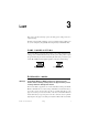
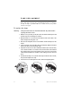
3 LAMP This section describes the lamp options, the lamp power setting, and how to replace the lamp. The lamp is electronically regulated to prevent overheating. Lamp regulation can be seen, for example, by the gradually decreasing intensity of the blinder effect. LAMP POWER SETTING ON ON The Atomic 3000 provides high and low lamp power settings. The high power setting provides maximum flash intensity; the low power setting reduces output by approximately 50 percent and extends lamp life.
LAMP REPLACEMENT End of life can be confirmed with the Flash LED on the rear panel. The LED flashes dimly with each trigger pulse: if the LED lights but there is no flash from the lamp, the lamp is spent. If the LED does not flash, there may be a problem with the control signal.
C ONTROLLER OPERATION 4 This section describes how to operate the Atomic 3000 with a DMX controller. DATA CONNECTION The Atomic 3000 provides both 3-pin and 5-pin XLR sockets for data connection. The pin-out on all sockets is pin 1 to shield, pin 2 to cold (-), and pin 3 to hot (+). There is no connection to pins 4 and 5. The sockets are wired in parallel: both inputs connect to both outputs.
DMX CONTROL MODES 4-channel DMX mode provides six special effects in addition to flash intensity, duration, and rate control. To select this 4-channel DMX operation, set pins 1, 2, 3, and 5 to off; set pin 4 to on. CONTROL ON 3-channel DMX mode provides control of flash intensity, flash duration, and flash rate for more advanced control than 1-channel mode. To select 3channel DMX operation, set pins 1 to 5 of the Mode DIP switch to off.
Find the address in the table. Read the settings for pins 1 - 5 to the left and read the settings for pins 6 - 9 above the address. “0” means OFF and “1” means ON. Pin 10 is always OFF for DMX operation.
DMX CONTROL SUMMARY For specific command values, see “DMX protocols” on page 23. INTENSITY Flash intensity can be set from minimum (blackout) to maximum on channel 1 in the 3- and 4-channel DMX modes. Intensity is maximum in 1-channel DMX mode. The maximum intensity can be reduced by selecting low power mode as described on page 9. DURATION Flash duration can be set from 0 to 650 ms on 50 Hz power supplies, or 0 to 530 ms on 60 Hz power supplies, on channel 2 in the 3- and 4-channel DMX modes.
whenever the combination of flash duration and rate prevents pauses between flashes. For example, the blinder effect can be achieved with a flash duration of 0.25 seconds (250 ms) and a flash rate of 4 flashes per second, or a flash duration of 0.05 seconds (50 ms) and a flash rate of 20 flashes per second. In 3- and 4-channel DMX mode, the intensity of the blinder effect is controllable on channel 1. Lamp power is electronically regulated to prevent the lamp from overheating.
5 STAND-ALONE OPERATION This section describes how to operate the Atomic 3000 in stand-alone mode without a DMX controller or Detonator remote control. STAND-ALONE FLASH RATE To program stand-alone execution 1 Apply power to the fixture. 2 Set pin 1 of the Mode DIP switch to ON. Set pins 2 - 5 to OFF. Set pin 6 to ON for low-power operation or to OFF for high-power operation. 3 Select either a flash rate or the blinder effect.
REMOTE ON/OFF Simple on/off remote control of the fixture can be achieved by connecting a switch or relay to pins 1 and 3 of one of the data input sockets. Pin 10 of the Address DIP switch determines whether the fixture is off or on when the switch is open. See Table 3. Pin 10 ON Pin 10 OFF Switch open (off) ON OFF Switch closed (on) OFF ON Table 3: Remote stand-alone control Multiple fixtures can be controlled from the same switch if they are serially connected output-to-input.
R EMOTE CONTROLS 6 This section describes how to operate the Atomic 3000 with optional Martin remote controls. MC-1 REMOTE CONTROL When connected to the Martin MC-1 remote control, the Atomic 3000 flashes with fixed rate, duration, and intensity when the Strobe button is pressed on the MC-1. Pin 2 on the Mode DIP switch must be OFF. No other DIP switch setting is necessary. Connect the Atomic 3000 to the MC-1 as if it were a controller. See “Data connection” on page 11.
ATOMIC DETONATOR Intensity Chase/Sync toggle Run Stop Chase Sync Flash Rate Run/stop toggle Intensity control Si n Fl a Flash rate control Bl Ef i n f e gl h s r dect e Single flash and synchronization Blinder effect The optional Detonator remote control provides the following: • • • • • Slider controls for flash rate and intensity Momentary push button control of the blinder effect Momentary push button for single flash and flash synchronization Run/stop toggle switch Chase/sync toggle swi
If the Detonator is connected to multiple fixtures, all fixtures except the master shall be set as slave fixtures, with pin 2 of the Mode DIP switch ON and pin 3 OFF. ON 1 2 3 4 5 6 Detonator master mode setting ON The remote control is powered by a “master” fixture via the data connection. The Detonator master fixture is selected by setting pins 2 and 3 of the Mode DIP switch to ON. Use this setting to operate a single fixture with the remote control.
To prog ram a multi-fixture ch ase 1 Connect the fixtures and Detonator. 2 Select the fixture to start the flash sequence and set it to master mode as described above. 3 Set the number of fixtures in the chase on the master fixture’s Address DIP switch. There may be 2 to 20 fixtures in a chase. 4 Set each additional fixture to slave mode on its Mode DIP switch. On its address DIP switch, set the slave’s position in the chase sequence.
7 SERVICE Warning: High voltage! Do not remove the rear panel. There are no userserviceable parts inside. FUSE REPLACEMENT The Atomic 3000 uses a 20 amp time-delay fuse for protection against current overload. If the power diode does not light when power is applied, the fuse may be spent. If the fuse blows repeatedly, there is a fault with the unit that requires service by a Martin technician. Never bypass the fuse or replace it with one of another size or rating.
A DMX PROTOCOLS 1-CHANNEL DMX MODE Channel Value Percent Function 1 0-5 6 - 249 250 - 255 0-1 2 - 98 98 - 100 Blackout Flash rate, slow to fast Continuous “Blinder” effect AND 4 3 CHANNEL DMX MODES Channel Value Percent Function 1 0-5 6 - 255 0-1 2 - 100 2 0 - 255 0 - 100 Flash duration 0 - 650 ms @ 50 Hz AC, or 0 - 530 ms @ 60 Hz AC 3 0-5 6 - 255 0-1 2 - 100 Flash rate No flash (single flash with ch. 1) 0.5 - 25 Hz @ 50 Hz AC, or 0.
A TOMIC 3000 SPECIFICATIONS B PHYSICAL Size (without bracket) . . . . . . . . . . . . . . . . . . . . 245 x 425 x 240 mm (9.7 x 16.7 x 9.5 in) Weight . . . . . . . . . . . . . . . . . . . . . . . . . . . . . . . . . . . . . . . . . . . . . . . . . . . . 7.5 kg (16.5 lb) THERMAL Maximum ambient temperature . . . . . . . . . . . . . . . . . . . . . . . . . . . . . . . . . 40° C (104° F) CONTROL AND PROGRAMMING DMX-512 (1990) control . . . . . . . . . . . . . . . . . . . . . . . . . . . . .
ACCESSORIES Atomic Detonator . . . . . . . . . . . . . . . . . . . . . . . . . . . . . . . . . . . . . . . . . . . . Atomic Colors for Atomic 3000 . . . . . . . . . . . . . . . . . . . . . . . . . . . . . . . . . MC-1 Controller, EU. . . . . . . . . . . . . . . . . . . . . . . . . . . . . . . . . . . . . . . . . . MC-1 Controller, US . . . . . . . . . . . . . . . . . . . . . . . . . . . . . . . . . . . . . . . . . . G-clamp. . . . . . . . . . . . . . . . . . . . . . . . . . . . . . . . . . . . . . . . . . .
Disposing of this product Martin products are supplied in compliance with Directive 2002/96/EC of the European Parliament and of the Council of the European Union on WEEE (Waste Electrical and Electronic Equipment), as amended by Directive 2003/108/EC, where applicable. Help preserve the environment! Ensure that this product is recycled at the end of its life. Your supplier can give details of local arrangements for the disposal of Martin products.
www.martin.