Atomic Colors user manual
Atomic Colors Unit Atomic 3000 DMX and Atomic Colors Unit combined. © 2003 Martin Professional A/S, Denmark. All rights reserved. No part of this manual may be reproduced, in any form or by any means, without permission in writing from Martin Professional A/S, Denmark. Printed in Canada. P\N 35000143, Rev.
SAFETY INFORMATION.................................................. 4 INTRODUCTION ................................................................ 5 PREPARATION FOR USE ............................................... 6 MOUNTING THE UNIT ..................................................... 9 CONNECTING THE UNIT .............................................. 10 OPERATING THE UNIT ................................................. 14 CHANGING THE GEL STRING .................................... 20 SERVICE ...
SAFETY INFORMATION 1 Before using this unit please read this manual completely, and refer to the user manual for Atomic 3000 DMX strobe. Warning: This product is for professional use only! It is not designed for household use. This product is designed exclusively for use with the Martin Atomic 3000 DMX unit. Use the device only as intended. The Atomic 3000 DMX presents risks of lethal or severe injury due to fire and heat, electric shock, ultraviolet radiation, and falls.
2 INTRODUCTION The Atomic Colors is a dedicated add-on unit for the Martin Atomic 3000 DMX strobe. This unit enhances the versatility of the Atomic 3000 DMX by adding the extra dimension of color changes that can be controlled and programmed with any standard DMX controller. Color changing is achieved by moving (or scrolling) a string of colored ‘gels’ (theatrical grade, plastic color media) in front of the strobe unit.
PREPARATION FOR USE 3 Unpacking The Atomic Colors comes with the following items: • • • 5 M (16.4 ft) XLR-4 connecting cable Standard gel string (factory installed) User manual The packing material protects the fixture during shipment; always use it to transport the fixture. System overview (Detailed connection diagrams are given in Section 5.) Power supply The Atomic Colors requires a separate external power supply. These are supplied separately and come in various standard unit sizes.
Control data Any device that outputs the DMX512 (1990) data protocol (including the one that may already be controlling your Atomic 3000 DMX strobe) can be used to control the Atomic Colors. ‘DMX’ is an industry standard data protocol, which allows up to 512 channels to be controlled through one serial data link. These 512 channels may be used by up to a maximum of 32 devices on only one cable run by ‘daisy-chaining’ the devices together.
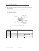
XLR-4 Cable Construction Notes: • • • • It is very important to ensure that the drain wire from the cable shield is connected to both XLR connector cases. Damage will occur if power connections short to the data, ground, or shield connections. When assembling XLR 4-pin cables, heat shrink should be used on each individual pin to prevent short circuits. (See diagram below) Please take care when constructing these cables. A high percentage of problems are a direct result of poor cable construction.
MOUNTING THE UNIT 1. 2. 3. 4. 5. 6. 4 Place the Atomic 3000 DMX unit so that it is resting on its bottom edge as shown below. Using an 8mm AF wrench, carefully remove the lower, front, M5 ‘Taptite’ screws on sides of the Atomic 3000 DMX. Loosen the top, front M5 ‘Taptite’ screws so that they protrude 5-6mm. Position the Atomic Colors in front of the strobe as shown with the top hooks resting on the loose ‘Taptite’ screws. Align the lower front screw holes and replace the lower front screws.
CONNECTING THE UNIT 5 System Connections This section describes how to connect the Atomic Colors to your lighting system using a 2-unit or an 8-unit external power supply. Notes: • Ensure the AC input power is switched off while you are connecting components of the system. • Do not connect the power supplies to any type of dimmer circuit. • Before operating the Atomic strobe, make sure the power supply for the Atomic Colors is connected, and switched on.
MPU-02 Connection Procedure 1. Rig the combined Atomic 3000 DMX and Atomic Colors fixture in the desired position, ensuring that you use the safety wire as a secondary means of attachment. 2. Connect the power/data output on the MPU-02 to the power/data input on the Atomic Colors with an XLR-4 cable. 3. Connect the MPU-02 to the main data link using the XLR-5 input. You can, for example, run a 5-pin XLR cable from the DMX output of an Atomic 3000 DMX to the input of the power supply.
MPU-08 Connection procedure Important Note: ‘Return’ lines The MPU-08 is designed for use with larger quantities of Atomic Colors fixtures, and in bigger installations where the cable runs a longer. In order to reduce the voltage drop in these longer cable runs, an XLR-4 ‘Return’ cable must be installed in the system, so the cabling forms a continuous loop. 1.
System connection diagram using the MPU-08 power supply (For clarity, only the Atomic Colors are shown) Atomic Colors User Manual Connecting the unit 13
OPERATING THE UNIT 6 All user settings are accessed using the LED display and the three push buttons on the side panel. Control ‘ACTION/RECALL’ ‘DOWN’ ‘UP’ 3 digit display Function Mode access and ‘Record’ Decrements the mode level, or value Increments the mode level, or value Displays modes, monitor, or blank display. Powering up the system When you power up the system, the following things happen: • • The gel string moves from one end to the other to determine the length of the string installed.
Monitor Display If left undisturbed for 5-7 seconds, the display will revert to ‘Monitor Mode’ The left hand vertical bar indicates that there is power (24V DC) at the unit. The middle vertical bar indicates that there is data (DMX) at the unit. The horizontal bars indicate the data signal level (DMX) at the unit. Display Flip The display-viewing angle can be flipped through 180º by pressing and holding the ‘ACTION/RECALL’ button, then pressing the ‘DOWN’ button.
Unit settings: Note: After changing any of the settings, press ‘ACTION/RECALL’ to store the new value. DMX address Selects the unit’s DMX address (start channel). The Atomic Colors uses 1, or 2 DMX channels depending on the fan speed control setting. The first DMX channel (start channel) controls the movement of the gel string, and the second channel, if remote fan control (Fnr) is selected, controls the cooling fan speed.
Factory settings To restore factory default settings, press and hold the ‘ACTION/RECALL’ button and press the ‘UP’ button for 1 second.
Summary of control functions: Setting Description DMX address Sets the unit’s DMX address Actions required Fan speed Sets the fan speed Display Press ‘UP’ or ‘‘DOWN’ once to increment/ decrement the value, hold down the ’UP’ or ‘DOWN’ for fast forward/reverse. Note: The unit uses 1, or 2 DMX channels depending on which control mode it is set for (see below). (See also, DMX addressing instructions) There are four fan speeds, 1 is the slowest, 4 is the fastest and a remote option.
Programming notes: The Atomic Colors uses 1 or 2 DMX channels, depending on which control mode it is set for. The first DMX channel (start channel) controls the movement of the gel string, and the second channel, if selected allows for remote control of the cooling fan speed. The unit will automatically select the two DMX channel mode if the fan speed setting is set for ‘Fnr’ (see below), otherwise the unit will remain in single DMX channel mode.
CHANGING THE GEL STRING 7 Introduction The unit comes supplied with a gel string installed. This gel string has 10 separate color filters joined with special high temperature tape to form one continuous piece. The colors in this gel string have been chosen to offer a wide choice of color and intensity, and various other gel strings are available from your dealer. Custom made gel strings can also be supplied, to special order.
Rotate whole the unit so that the motor/fan/ electronics section on your right-hand side. Place the gel tab beside the anchor on the other shaft (Spring shaft). With your left hand, firmly hold the gel tab next to the anchor hook but do not attach it yet. With your right hand, turn the anchor hub of the spring shaft away from you (counter-clockwise) for four complete turns. As you turn the shaft you should feel the spring tension increasing. 7.
Installation of a gel string Atomic Colors User Manual Changing the gel string 22
Gel string construction Atomic Colors User Manual Changing the gel string 23
7 SERVICE Problem Troubleshooting Troubleshooting is a process of elimination. First, rule out the other field factors (i.e. faulty cables, power sources). For full technical advice and/ or parts, please contact your selling dealer. The LED display aids in the troubleshooting of the Atomic Colors unit. The display is located on the on the side panel of each unit. Note: A high percentage of problems are a direct result of poor cable and corrupt DMX control signals.
8 SPECIFICATIONS Physical Size: Weight: 470 x 273 x 102 mm (18.5 x 10.7 x 4.0 in.) 2.5 kg (5.6 lb) Thermal Max.