P/N 35000080 CX-2 user manual
Introduction. . . . . . . . . . . . . . . . . . . . . . . . . . . . . . . . . . . . . . . 3 Parts key . . . . . . . . . . . . . . . . . . . . . . . . . . . . . . . . . . . . . . . . . 5 Lamp installation . . . . . . . . . . . . . . . . . . . . . . . . . . . . . . . . . . 6 AC power connection. . . . . . . . . . . . . . . . . . . . . . . . . . . . . . . 7 Installation. . . . . . . . . . . . . . . . . . . . . . . . . . . . . . . . . . . . . . . . 9 DIP-switch settings. . . . . . . . . . . . . . . . . . . . .
1 INTRODUCTION Thank you for selecting the Martin CX-2. The CX-2 is an automated profile spotlight designed for a 250 watt halogen source. It provides separate color and gobo/effect wheels, continuous electronic dimming, adjustable focus, strobe effects, and multiple control options. CX-2 SAFETY INFORMATION Warning! This product is for professional use only. It is not for household use. This product presents risks of lethal or severe injury due to fire and heat, electric shock, and falls.
To prot ect yoursel f and ot hers fr om burns and fi re • Never attempt to bypass the thermostatic switch or fuses. Always replace defective fuses with ones of the specified type and rating. • Keep all combustible materials (for example fabric, wood, paper) at least 0.1 meters (4 inches) away from the fixture. Keep flammable materials well away from the fixture. • Replace the lamp if it becomes defective or worn out.
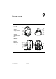
2 PARTS KEY 1 focus lens 2 cover locks 3 air vent 4 safety cable holes 5 mounting bracket 6 air vents 7 AC input & main fuse 8 DIP-switch 9 data output 10 data input 11 swivel locks 12 cooling fan CX-2 user manual Parts key 5
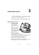
3 LAMP INSTALLATION The CX-2 uses a 24V, 250W ELC halogen lamp. Two models are available, an economical 300 hour lamp from Philips and a high-output 50 hour lamp from Osram. Installing any other lamp may damage the fixture. Allow the lamp to cool for at least 5 minutes before packing and moving the fixture. To avoid possible damage, remove the lamp when shipping the fixture.
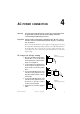
4 AC POWER CONNECTION Warning! For protection from dangerous electric shock, the fixture must be grounded (earthed). The AC mains supply shall have overload and ground-fault protection. Important! Check voltage setting before applying power. Do not connect the CX-2 to an electrical dimmer system: doing so can damage the electronics. Before use verify that the fixture’s power supply is correctly tapped for the local AC voltage.
To inst all a plug on t he mains lead The fixture’s mains lead must be fitted with a grounding-type cord cap that fits your power distribution cable or outlet. Consult a qualified electrician if you have any doubts about proper installation. Important! Verify that the feed cables are undamaged and rated for the current requirements of all connected devices before use.
5 INSTALLATION The CX-2 can be fastened directly to a suitable surface or to a rigging clamp by means of its adjustable mounting bracket. Do not lay the fixture flat on its mounting bracket arms or position it so that there is less than 10 cm (4 in.) clearance around the fan and air vents. For maximum lamp life, do not place the fixture directly on or beside a speaker cabinet or other source of strong vibrations. To rig t he CX- 2 Warning! Always use a secure means of secondary attachment.
DIP- SWITCH SETTINGS 6 This section describes how to select the DMX address and special settings using the DIP-switch on the end panel. Important! Disconnect the fixture from AC power before changing the DIP-switch setting. Changes take effect after the fixture has been turned off and back on. DMX ADDRESS SELECTION If the CX-2 is to be used with a DMX protocol controller, then the DIP-switch must be set to a DMX control address.
DIP-SWITCH ADDRESS TABLE Find the address in the table below. Read the settings for pins 1 - 5 to the left and read the settings for pins 6 - 9 above the address. “0” means OFF and “1” means ON. Important! Pins 10 and 11 must be OFF for full DMX control. Pin 10 must be OFF and pin 11 must be ON for 1-channel DMX control.
SPECIAL SETTINGS DIP-switch pins 1 - 9 are used to select special options in stand-alone and master/slave mode. To enable these options, pin 10 must be ON. Pin 11 toggles between 1 and 4 channel DMX control. It must be OFF for master/slave operation. Lamp life can be extended by reducing the voltage slightly. Set DIP-switch pin 12 to ON for longer lamp life, or OFF for full output intensity. Note: the fixture shall be disconnected from AC power when changing DIP-switch settings.
7 DATA CONNECTION This section describes how to connect fixtures to a controller. RECOMMENDED CABLE A reliable data connection begins with the right cable. Standard microphone cable cannot transmit DMX data reliably over long runs. For best results, use cable specifically designed for RS-485 applications. Your Martin dealer can supply high quality cable in various lengths. CONNECTIONS The CX-2’s XLR data sockets are wired with pin 1 to ground, pin 2 to signal (cold), and pin 3 to signal + (hot).
To connect t he dat a link 1 Connect a data cable to the controller’s data output. If controller has a 5-pin output, use a 5-pin male to 3-pin female adaptor cable (P/N 11820005). 2 Lead the data cable from the controller to the first fixture. Plug the cable into the fixture’s data input. 3 Connect the output of the fixture closest to the controller to the input of the next fixture. If connecting to a fixture with reversed-polarity (pin 3 cold), insert a phase-reversing cable between the two fixtures.
8 OPERATION FULL DMX OPERATION For DMX operation, the CX-2 must be connected to a DMX controller as described under “Data connection” on page 13. DIP-switch pins 1 - 9 must be set to the DMX address as described on page 10. Pins 10 and 11 must be set to OFF. DMX CHANNEL DESCRIPTION See also the DMX protocol on page 21. Channel 1 controls the light intensity and the strobe rate. It also allows you to execute a “stand-alone” program with random color and gobo change using automatic or music trigger.
The single-channel functions are shown below.
To set t he mast er Important! Set only 1 fixture as master (with DIP-switch pin 2 and 10 ON): errors and damage can occur if there is more than 1 master. 2 Set DIP-switch pins 3, 5, 6, 7, 8, 9, and 11 to OFF. 21 1 Set DIP-switch pins 2 and 10 to ON. ì ë ê é è ç æ å ä ìí ìì ìë 3 Set DIP-switch pins 1, 4, and 12 ON or OFF, as desired, to select the options described on page 12. To set a sl ave OPTION 1 (SPECIAL OPTIONS DISABLED) 1 Set DIP-switch pin 1 to ON. 21 2 Set pins 2 - 11 to OFF.
9 BASIC SERVICE The CX-2 requires simple routine maintenance. The maintenance schedule depends heavily on the operating environment; please consult a Martin service technician for recommendations. Any service procedure not described here should be referred to a qualified technician. Important! Excessive dust, grease, and smoke fluid buildup degrades performance and causes overheating and damage to the fixture that is not covered by the warranty.
To clean t he f an and air vents To maintain adequate cooling, dust must be cleaned from the fan and air vents periodically. 1 Remove the data and power cables and stand the fixture on end. 2 Remove dust and dirt from the fan blades and vent grills using a soft brush, cotton swab, vacuum, or compressed air. REPLACING FUSES The CX-2 has 2 fuses. The main fuse holder is built in to the mains input socket. The secondary fuse is located on the printed circuit board.
10 TROUBLESHOOTING Problem One or more of the fixtures is completely dead. 20 Probable cause(s) Remedy No power to fixture. Check that power is switched on and cables are plugged in. Primary fuse blown. Replace fuse. Secondary fuse blown. Replace fuse. Fixtures reset correctly but all respond erratically or not at all to the controller. The controller is not connected. Connect controller. XLR pin-out of the controller does not match pin-out of the first fixture on the link (i.e.
A DMX PROTOCOL Channel Value Percent Function 0-4 5 - 154 155 - 169 170 - 229 230 - 239 240 - 249 250 - 255 0-1 2 - 60 61 - 66 67 - 89 90 - 93 94 - 97 98 - 100 Dimmer, Strobe, Reset Light off Dimmer, closed to open Dimmer full open Strobe, fast to slow Stand-alone, music trigger Stand-alone, auto trigger Reset 0-5 6 - 11 12 - 17 18 - 23 24 - 29 30 - 35 36 - 41 42 - 47 48 - 53 54 - 59 60 - 65 66 - 71 72 - 77 78 - 83 84 - 89 90 - 95 96 - 101 102 - 107 108 - 113 114 - 119 120 - 125 126 - 131 132 - 137
Channel Value Percent 0 - 11 12 - 23 24 - 35 36 - 47 48 - 59 60 - 71 72 - 83 84 - 95 96 - 107 108 - 119 120 - 131 132 - 143 144 - 155 156 - 167 168 - 179 180 - 191 192 - 203 204 - 215 216 - 255 0-4 5-8 9 - 13 14 - 18 19 - 23 24 - 27 28 - 32 33 - 37 38 - 41 42 - 46 47 - 51 52 - 55 56 - 60 61 - 65 66 - 70 71 - 74 75 - 79 80 - 84 85 - 100 0-2 3 - 255 0-1 2 - 100 Color / Gobo Speed Tracking (speed function off) Fast to slow 4 22 Function Gobo Wheel Open Frost Virus Dot circle Spokes Atomic Dot cross D
S PECIFICATIONS B PHYSICAL Size (L x W x H): . . . . . . . . . . . . . . . . . . . . . . . 296 x 269 x 270 mm (11.7 x 10.6 x 12.1 in) Weight: . . . . . . . . . . . . . . . . . . . . . . . . . . . . . . . . . . . . . . . . . . . . . . . . . . . . .5.5 kg (12.1 lbs) THERMAL Maximum ambient temperature (Ta): . . . . . . . . . . . . . . . . . . . . . . . . . . . . . . . 40° C (104° F) Maximum surface temperature: . . . . . . . . . . . . . . . . . . . . . . . . . . . . . . . . . . .
CX-2 4-Channel DMX Protocol 58 #4 %22 83 458 483 4:8 RSHQ 2 &4 2 53 &5 2 &6 2 58 RSHQ 63 2 &8 83 *4 IURVW &7 *5 43 2 &9 73 2 &: :8 *6 53 *7 *8 533 2 &; 83 2 433 *9 *: 63 73 &< 2 2 &45 458 :3 2 &46 483 *RER2(IIHFW#ZKHHO *; *< *43 2 &47 2 ;3 &48 2 6&4 4:8 [O#LULV 83 6WDQG0DORQH slow PXVLF DXWR fast 93 &RORU#ZKHHO &43 2 &44 558 #6WUREH RSHQ FORVHG R S H Q #6 433 'LPPHU 43 #5 :8 O#LULV 2 6&5 533 P#LULV 93 <3 V#LULV 6WDQG0DORQH 55