
User manual
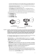
Table Of Contents

DMX data link 11
DMX data link
The MAC III Performance has 5-pin locking XLR sockets for DMX and RDM input and output. The default
pin-out on both sockets is:
• pin 1 to shield
Port 1, DMX and RDM communication:
• pin 2 to data 1 cold (-)
• pin 3 to data 1 hot (+)
Port 2, not used by default but available for data communication:
• pin 4 to data 2 cold (-)
• pin 5 to data 2 hot (+).
The default use of Port 1 for DMX and RDM can be altered in the control panel (see “Personality – tailoring
performance” on page 16).
Tips for reliable data transmission
• Use shielded twisted-pair cable designed for RS-485 devices: standard microphone cable cannot transmit
control data reliably over long runs. 24 AWG cable is suitable for runs up to 300 meters (1000 ft). Heavier
gauge cable and/or an amplifier is recommended for longer runs.
• To split the serial link into branches, use a splitter such as the Martin 4-Channel Opto-Isolated RS-485
Splitter/Amplifier.
• Do not overload the link. Up to 32 devices may be connected on a serial link.
• Install a DMX termination plug on the last fixture on the link.
To connect the data link
1. Connect the DMX data output from the controller to the MAC III Performance’s data input (male XLR)
socket.
2. Run the data link from the MAC III Performance’s data output (female XLR) socket to the data input of
the next fixture.
3. Terminate the data link by connecting a 120 Ohm, 0.25 Watt resistor between the data 1 hot (+) and cold
(-) conductors (and between data 2 hot and cold if used) at the data output of the last fixture on the link.
If a splitter is used, terminate each branch of the link.