MX-1 user manual
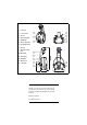
1 focus lens 2 cover screws 3 air vent 4 mirror assembly 5 pan/tilt arm 6 safety cable holes 7 mounting bracket 8 air vents 9 AC input & main fuse 10 DIP-switch 11 data output 12 data input 13 swivel locks 14 cooling fan ©1999 - 2001 Martin Professional A/S, Denmark. All rights reserved. No part of this manual may be reproduced, in any form or by any means, without permission in writing from Martin Professional A/S, Denmark. Printed in Denmark. P/N 35000077, Rev.
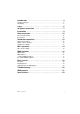
Introduction . . . . . . . . . . . . . . . . . . . . . . . . . . . . . . . . . . . . . . . .4 Safety precautions . . . . . . . . . . . . . . . . . . . . . . . . . . . . . . . . . . . . . . . . . . . . . 4 Unpacking . . . . . . . . . . . . . . . . . . . . . . . . . . . . . . . . . . . . . . . . . . . . . . . . . . . . 5 Lamp . . . . . . . . . . . . . . . . . . . . . . . . . . . . . . . . . . . . . . . . . . . . . .6 AC power connection . . . . . . . . . . . . . . . . . . . . . . . . . . . . . . . .
1 INTRODUCTION Thank you for selecting the Martin MX-1. The MX-1 is an automated profile spotlight that employs a 250 watt halogen lamp. It provides strobe effects, continuous electronic dimming, 18 color/gobo effects, a moving-mirror with 230° of pan and 76° of tilt, adjustable focus, a 16° beam angle, and a variety of control options. The MX-1 is not for household use. It is not for children: it presents risks of injury due to electric shock, burns, falls, high-intensity light, and fire.
• Never place flammable materials anywhere near the fixture. • Never illuminate surfaces within 0.3 meters (12 inches) of the fixture. • Never operate the fixture if the ambient temperature (Ta) exceeds 40° C (104° F). • Never place filters or other objects over the lens or mirror. • Never stare directly into the light. • Never operate the fixture without all parts installed. • Never modify the fixture or install other than genuine Martin parts.
2 LAMP The MX-1 comes from the factory with a Philips 500 hour lamp installed. This a 24V, 250W ELC halogen lamp. A high-output 50 hour lamp from Osram is also available. Installing any other lamp may damage the fixture! Allow the lamp to cool for at least 5 minutes before packing and moving the fixture. To avoid possible damage, remove the lamp when shipping the fixture. There are two lamp intensity options that may be selected with DIP-switch pin 12.
3 AC POWER CONNECTION Warning! For protection from dangerous electric shock, the fixture must be grounded (earthed). The AC mains supply shall have a fuse or circuit breaker, and ground-fault protection. Important! Check voltage setting before applying power. Do not connect the MX-1 to an electrical dimmer system: doing so can damage the electronics. Before use verify that the fixture’s power supply is correctly tapped for the local AC voltage.
To install a plug on the mains lead The fixture’s mains lead must be fitted with a grounding-type cord cap that fits your power distribution cable or outlet. Consult a qualified electrician if you have any doubts about proper installation. Important! Verify that the feed cables are undamaged and rated for the current requirements of all connected devices before use.
4 INSTALLATION The MX-1 can be fastened directly to a suitable surface or to a rigging clamp by means of its adjustable mounting bracket and it can be placed at an angle directly on the stage or floor using the mounting bracket as a floor stand. Do not lay the fixture flat on its pan/tilt arms. For maximum lamp life, do not place the fixture directly on or beside a speaker cabinet or other source of strong vibrations. Warning! Block access below the work area before proceeding.
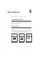
5 DATA CONNECTION This section describes how to connect fixtures to a controller. RECOMMENDED CABLE A reliable data connection begins with the right cable. Standard microphone cable cannot transmit DMX data reliably over long runs. For best results, use cable specifically designed for RS-485 applications. Your Martin dealer can supply high quality cable in various lengths. CONNECTIONS The MX-1’s XLR data sockets are wired with pin 1 to ground, pin 2 to signal (cold), and pin 3 to signal + (hot).
To connect the data link 1 Connect a data cable to the controller’s data output. If the controller has a 5pin output, use a 5-pin male to 3-pin female adaptor cable (P/N 11820005). 2 Lead the data cable from the controller to the first fixture. Plug the cable into the fixture’s data input. 3 Connect the output of the fixture closest to the controller to the input of the next fixture. If connecting to a fixture with reversed-polarity (pin 3 cold), insert a phase-reversing cable between the two fixtures.
STAND-ALONE OPERATION 6 The MX-1 may be operated without a controller in stand-alone mode. It may be operated as a single unit or together with other MX-1s in “master/slave” configuration. Several options are available to modify stand-alone operation. These options are selected using the DIP-switch as described below. Important! The MX-1 transmits a signal when DIP-switch pins 2 and 10 are set to ON.
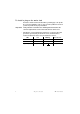
To set the master Important! Set only 1 fixture as master (DIP-switch pin 2 and 10 ON). ON 2 Set DIP-switch pins 3, 6, 7, 8, 9, and 11 to OFF. 1 2 3 4 5 6 7 8 9 10 11 12 ON 1 Set DIP-switch pins 2 and 10 to ON. 1 2 3 4 5 6 7 8 9 10 11 12 3 Select options with DIP-switch pins 1, 4, 5, and 12. To set a sl ave 1 Set DIP-switch 10 to ON. 2 Set pins 1, 2, 3, 4, 5 and 11 to OFF. 3 Select options with DIP-switch pins 6, 7, 8, 9, and 12.
7 MC-1 OPERATION All new MX-1s and older MX-1s with CPU firmware v 1.7 or higher are fully compatible with the Martin MC-1 Controller. See the MC-1 user manual for additional information. MC-1 SETTINGS DIP-switch pin 10 must be set to OFF to enable MC-1 mode operation. Changes to the setting take effect after the fixture has been turned off and on. DIP-switch pins 5, 7, 8, and 9 select several control options that can be combined to achieve powerful effects quickly and easily.
DMX OPERATION 8 DMX MODES The MX-1 has 3 DMX modes to choose from: a 1-channel mode that provides control of the built-in stand-alone features, a 6-channel mode that provides position control of all effects plus speed control of the mirror, and an “extended” 7-channel mode that in addition provides speed control of the effect wheel. To select DMX mode 1 Disconnect the fixture from power. Set DIP-switch pin 10 to OFF. 2 To select 1-channel DMX mode, set DIP-switch pin 11 to ON.
Find the address in the table below. Read the settings for pins 1 - 5 to the left and read the settings for pins 6 - 9 above the address. “0” means OFF and “1” means ON. Pin 10 is always OFF for DMX operation.
1-CHANNEL DMX OPERATION The functions shown in the following table are available in 1-channel mode. When a “stand-alone” function is selected, the fixture steps through a routine using a built-in microphone to trigger the action to the beat of the music. Note that multiple fixtures cannot be synchronized in this mode.
BASIC 9 SERVICE The MX-1 requires simple routine maintenance. The maintenance schedule depends heavily on the operating environment; please consult a Martin service technician for recommendations. Any service procedure not described here should be referred to a qualified technician. Important! Excessive dust, grease, and smoke fluid buildup degrades performance and causes overheating and damage to the fixture that is not covered by the warranty.
To clean the fan and air vents To maintain adequate cooling, dust must be cleaned from the fan and air vents periodically. 1 Remove the data and power cables and stand the fixture on end. 2 Remove dust and dirt from the fan blades and vent grills using a soft brush, cotton swab, vacuum, or compressed air. REPLACING FUSES The MX-1 has 2 fuses. The main fuse holder is built in to the mains input socket. The secondary fuse is located on the printed circuit board.
10 TROUBLESHOOTING Problem One or more of the fixtures is completely dead. Fixtures reset correctly but all respond erratically or not at all to the controller. Fixtures reset correctly but some respond erratically or not at all to the controller. Probable cause(s) No power to fixture. Primary fuse blown. Replace fuse. Secondary fuse blown. Replace fuse. The controller is not connected. Connect controller. XLR pin-out of the controller does not match pin-out of the first fixture on the link (i.e.
A DMX PROTOCOL Channel Value Percent Function 0-4 5 - 154 155 - 169 170 - 229 230 - 239 240 - 249 250 - 255 0-1 2 - 60 61 - 66 67 - 89 90 - 93 94 - 97 98 - 100 Dimmer, Strobe, Reset Light off Dimmer, closed to open Dimmer full open Strobe, fast to slow Stand-alone, music trigger Stand-alone, auto trigger Reset 0 - 255 0 - 100 Not used 0 - 11 12 - 23 24 - 35 36 - 47 48 - 59 60 - 71 72 - 83 84 - 95 96 - 107 108 - 119 120 - 131 132 - 143 144 - 155 156 - 167 168 - 179 180 - 191 192 - 203 204 - 215 21
Ch. 7 closed up left white fast f fast Ch. 6 of Ch. 5 Ch. 4 Ch. 3 Ch. 2 Ch.
B S PECIFICATIONS PHYSICAL • Size (L x W x H)............................... 537 x 269 x 263 mm (21.1 x 10.6 x 10.4 in) • Weight................................................................................................ 6 kg (13 lbs) THERMAL • Maximum ambient temperature (Ta) ...............................................40° C (104° F) • Maximum surface temperature ........................................................65° C (149° F) CONTROL AND PROGRAMMING • Data pin-out ............