MX-4 user manual
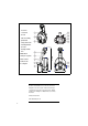
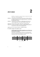
1 focus lens 2 cover bolts 3 air vent 4 mirror assembly 5 pan/tilt arm 6 safety cable holes 7 mounting bracket 8 air vents 9 AC input & main fuse 10 DIP-switch 11 lamp access plate 12 data sockets 13 swivel locks 14 cooling fan ©1999 - 2000 Martin Professional A/S, Denmark. All rights reserved. No part of this manual may be reproduced, in any form or by any means, without permission in writing from Martin Professional A/S, Denmark. Printed in Denmark. P/N 35000086, Rev.
INTRODUCTION . . . . . . . . . . . . . . . . . . . . . . . . . . . . . . . . . . . . . . . 4 AC POWER . . . . . . . . . . . . . . . . . . . . . . . . . . . . . . . . . . . . . . . . . . 6 INSTALLATION . . . . . . . . . . . . . . . . . . . . . . . . . . . . . . . . . . . . . . . . 9 STAND-ALONE OPERATION. . . . . . . . . . . . . . . . . . . . . . . . . . . . . . 10 MC-1 OPERATION . . . . . . . . . . . . . . . . . . . . . . . . . . . . . . . . . . . . 12 DMX OPERATION . . . . . . . . . . . . . . . . . . . . .
1 INTRODUCTION Thank you for selecting the Martin MX-4. This automated moving-mirror spotlight provides 15 full and 2 split colors, 19 gobos, high-speed shutter, 230° of pan and 76° of tilt, adjustable focus, and a 16° beam angle. It uses a 150 watt discharge lamp and may be operated with DMX controllers, the Martin MC-1 remote control, or as a stand-alone unit with master/slave capability. SAFETY INFORMATION Warning! This product is for professional use only. It is not for household use.
• Do not stare directly into the light. Never look at an exposed lamp while it is lit. • Replace the lamp if it becomes defective or worn out. To protect yourself and other s from burns and fire • Never attempt to bypass the thermostatic switch or fuses. Always replace defective fuses with ones of the specified type and rating. • Keep all combustible materials (for example fabric, wood, paper) at least 0.1 meters (4 inches) away from the fixture. Keep flammable materials well away from the fixture.
2 AC POWER The MX-4 power supply has 5 voltage and 2 frequency settings. The factory default setting is shown on the serial number label. Warning! For protection from fire and electric shock, the fixture must be grounded (earthed). The power supply shall have overload and ground-fault protection. Warning! Verify that the feed cables are undamaged and rated for the current requirements of all connected devices before use. Important! Check the power supply setting before applying power.
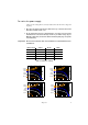
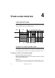
To rewire the power supply Always use the setting that most closely matches the local AC mains voltage and frequency. 1 Disconnect the fixture from AC power. Remove the top cover bolts with a 4 mm Allen wrench and lift off the cover. 2 On the transformer, which is located behind the color wheel, move the brown and white wires to the transformer taps shown for your mains voltage. (If your MX-4 has 2 blue wires, the blue wire with the insulated spade plug corresponds to the white wire.
1 2 3 4 5 6 7 8 250 V orange orange blue white black brown 9 10 11 12 13 14 15 16 3 To set the frequency, move the black wire on the ballast to the “230-50” (50 Hz) or “230-60” (60 Hz) terminal as shown. The wire is released and locked by inserting a small screwdriver in the square hole next to the terminal and prying back the spring. 4 Tug lightly on the black wire to make sure that it is connected securely. 5 Replace the top cover.
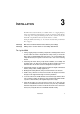
3 I NSTALLATION The MX-4 can be fastened directly to a suitable surface or to a rigging clamp by means of its adjustable mounting bracket. It can also be placed at an angle directly on the stage or floor using the mounting bracket as a floor stand. Do not lay the fixture flat on its pan/tilt arms: this can cause the fixture to overheat. If using the GE Arcstream lamp, see “To orient the Arcstream lamp for maximum life” on page 19. Warning! Block access below the work area before proceeding.
4 STAND-ALONE OPERATION CUSTOM SETTINGS Stand-alone operation may be customized with the settings in Table 3. The options may be combined and are set using DIP-switch pins 1 - 10. Changes may not take effect until after the fixture has been turned off and on.
not strike, disconnect the fixture from power for several minutes to reduce strain on the starter while the lamp cools. MASTER / SLAVE OPERATION Up to 32 MX-4s can be connected together and operated in master/slave mode in which slave fixtures follow instructions sent from the master. Important! Set only 1 fixture as master: damage can occur if 2 masters, or a master and a controller, are linked together. To set up MX-4s for master/slave oper ation 1 Disconnect all fixtures from power.
5 MC-1 OPERATION The MX-4 is fully compatible with the Martin MC-1 Controller. See the MC-1 user manual for additional information. SETTINGS DIP-switch pin 10 must be set to OFF to enable MC-1 mode operation. Changes to the setting take effect after the fixture has been turned off and on. DIP-switch pins 5, 6, 7, 8, and 9 select several control options that can be combined to achieve powerful effects quickly and easily.
6 DMX OPERATION This section describes how to set up and connect the MX-4 for operation with DMX controllers. DATA CONNECTION A reliable data connection begins with the right cable. Standard microphone cable cannot transmit DMX data reliably over long runs. For best results, use cable specifically designed for RS-485 applications. Your Martin dealer can supply high quality cable in various lengths.
To connect the data link 1 Connect a data cable to the controller’s data output. If the controller has a 5-pin output, use a 5-pin male to 3-pin female adaptor cable (P/N 11820005). 2 Lead the data cable from the controller to the first fixture and plug it into the data input. 3 Connect the output of the fixture closest to the controller to the input of the next fixture. If connecting to a fixture with reversed-polarity (pin 3 cold), insert a phase-reversing cable between the two fixtures.
6/7 CHANNEL DMX OPERATION The 6-channel DMX mode provides position control of all effects plus speed control of the moving mirror. The optional 7-channel mode adds speed control of the color and gobo wheels. Lamp power Lamp power can be switched on and off from the controller. When set up for 6- or 7-channel DMX operation, the lamp remains off until a lamp-on command is sent. Note: A peak of electric current many times the operating current is drawn briefly when striking a lamp.
To select DMX mode 1 Disconnect the fixture from power. Set DIP-switch pin 10 to OFF. 2 To select 1-channel DMX mode, set DIP-switch pin 11 to ON. 3 To select 6-channel DMX mode, set DIP-switch pin 11 to OFF. Verify that the 6/7 ch. jumper is set for 6 channels. This is the factory configuration. See “Setting the 6/7-ch. DMX jumper” on page 21. 4 To select 7-channel DMX mode, set DIP-switch pin 11 to OFF. Set the 6/7 ch. jumper for 7 channels as described on page 21.
DIP-Switch Setting #1 0 1 0 1 0 1 0 1 0 1 0 1 0 1 0 1 0 1 0 1 0 1 0 1 0 1 0 1 0 1 0 1 0 = OFF 1 = ON #2 #3 #4 0 0 0 0 0 0 1 0 0 1 0 0 0 1 0 0 1 0 1 1 0 1 1 0 0 0 1 0 0 1 1 0 1 1 0 1 0 1 1 0 1 1 1 1 1 1 1 1 0 0 0 0 0 0 1 0 0 1 0 0 0 1 0 0 1 0 1 1 0 1 1 0 0 0 1 0 0 1 1 0 1 1 0 1 0 1 1 0 1 1 1 1 1 1 1 1 #5 0 0 0 0 0 0 0 0 0 0 0 0 0 0 0 0 1 1 1 1 1 1 1 1 1 1 1 1 1 1 1 1 #9 #8 #7 #6 0 0 0 0 0 0 0 1 0 0 1 0 0 0 1 1 0 1 0 0 0 1 0 1 0 1 1 0 0 1 1 1 1 0 0 0 1 0 0 1 1 0 1 0 1 0 1 1 1 1 0 0 1 1 0 1
7 LAMP COMPATIBLE LAMPS The MX-4 uses the Philips CDM-SA/T (short-arc, tubular) 150W discharge lamp. If desired, the GE Arcstream 150 may be substituted. Installing any other lamp may damage the fixture. To replace the lamp WARNING! Wear safety glasses and allow the lamp to cool for at least 5 minutes before removing the lamp. 1 Disconnect the fixture from power and allow it to cool. 2 Remove 2 screws from the lamp-socket assembly with a Pozidriv #2 screwdriver. Remove the lamp assembly.
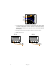
To orient the Arcstream lamp for maximum l ife If using the GE Arcstream lamp, maximum lamp life will be achieved by installing the lamp so that the arc is parallel with the ground. This is the case in most installations. If the fixture is installed sideways, however, as shown to the right, below, the arc will be vertical. Turn the lamp socket 90° to achieve the ideal burning position. 1 Disconnect the fixture from power and allow it to cool.
BASIC 8 SERVICE The MX-4 requires simple routine maintenance. The maintenance schedule depends heavily on the operating environment; please consult a Martin service technician for recommendations. Any service procedure not described here should be referred to a qualified technician. Important! Excessive dust, grease, and smoke fluid buildup degrades performance and causes overheating and damage to the fixture that is not covered by the warranty.
To cl ean the fan and air vents To maintain adequate cooling, dust must be cleaned from the fan and air vents periodically. 1 Remove the data and power cables and stand the fixture on end. 2 Remove dust and dirt from the fan blades and vent grills using a soft brush, cotton swab, vacuum, or compressed air. REPLACING FUSES The MX-4 has 2 fuses. The main fuse holder is built in to the mains input socket. The secondary fuse is located on the printed circuit board.
9 TROUBLESHOOTING Problem One or more of the fixtures is completely dead. Fixtures reset correctly but all respond erratically or not at all to the controller. Fixtures reset correctly but some respond erratically or not at all to the controller. Remedy No power to fixture. Check that power is switched on and cables are plugged in. Primary fuse blown. Replace fuse. Secondary fuse blown. Replace fuse. The controller is not connected. Connect controller.
A DMX PROTOCOL Channel 1 2 Value Percent Function 0-9 10 - 19 20 - 99 100 - 159 160 - 179 180 - 204 205 - 229 230 - 239 240 - 249 250 - 255 0-3 3-7 7 - 39 39 - 62 63 - 70 70 - 80 80 - 90 90 - 94 94 - 98 98 - 100 Shutter, Lamp power, Reset Shutter closed (blackout) Lamp-on Shutter open Strobe, fast to slow Shutter closed Remote stand-alone w/ music trigger Remote stand-alone w/ auto trigger Shutter closed Reset (hold for 5 sec.) Lamp-off (w/ ch. 2 & 3 > 252, hold for 5 sec.
Channel Value Percent Function 0 - 11 12 - 23 24 - 35 36 - 47 48 - 59 60 - 71 72 - 83 84 - 95 96 - 107 108 - 119 120 - 131 132 - 143 144 - 155 156 - 167 168 - 179 180 - 191 192 - 203 204 - 215 216 - 227 228 - 239 240 - 255 0-4 5-8 9 - 13 14 - 18 19 - 23 24 - 27 28 - 32 33 - 37 38 - 41 42 - 46 47 - 51 52 - 55 56 - 60 61 - 65 66 - 70 71 - 74 75 - 79 80 - 84 85 - 88 89 - 96 97 - 100 Gobo Wheel Open Worms 2 Web Petals Spokes Cone 2 Maze Crater Holes 2 Cross 2 Jagged cross Atomic Dot circle Nordic Aim Spok
B S PECIFICATIONS PHYSICAL Size (L x W x H) .................................................. 537 x 269 x 263 mm (21.1 x 10.6 x 10.4 in) Weight............................................................................................................... 8.8 kg (19.4 lbs) SOURCE Philips CDM-SA/T 150W ................................................................ 85 Lm/W, 6000 hr, 4000 K GE Arcstream 150 W .......................................................................