Martin DMX 5.3 Splitter TM Martin RDM 5.
Dimensions All dimensions are in millimeters 45mm 220mm 124.5mm Martin RDM 5.5 Splitter illustrated. Martin DMX 5.3 Splitter has same dimensions © 2011 Martin Professional A/S. Information subject to change without notice. Martin Professional A/S and all affiliated companies disclaim liability for any injury, damage, direct or indirect loss, consequential or economic loss or any other loss occasioned by the use of, inability to use or reliance on the information contained in this manual.
Contents Dimensions . . . . . . . . . . . . . . . . . . . . . . . . . . . . . . . . . . . . . . . . . . . .2 Safety information . . . . . . . . . . . . . . . . . . . . . . . . . . . . . . . . . . . . . . .4 Introduction . . . . . . . . . . . . . . . . . . . . . . . . . . . . . . . . . . . . . . . . . . . .7 Features . . . . . . . . . . . . . . . . . . . . . . . . . . . . . . . . . . . . . . . . . . . . .7 Unpacking . . . . . . . . . . . . . . . . . . . . . . . . . . . . . . . . . . . . . . . . . . .
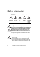
Safety information The following symbols are used to identify important safety information in this manual: Danger! Risk of Danger! Risk of Danger! Risk of personal injury. electric shock. fire. Warning! Risk of burns. Warning! Refer to user manual before installing, powering or servicing. Warning! This device is not for household use. Warning! Read this manual before operating the device, follow the safety precautions listed below, and observe all warnings in this manual and printed on the device.
• Connect the device to AC power using either the supplied power input cable (DMX 5.3 Splitter only) or via 3-conductor cable that is heat resistant to minimum 90° C (194° F) and rated minimum 20 amp. In North America the power input cable must be minimum 12 AWG, type SJT or equivalent. In the EU the cable must be minimum 2.5 mm2 conductor size and HAR approved or equivalent. • Cables used for power throughput via the RDM 5.
PROTECTION FROM INJURY DUE TO FALLS • When suspending the device overhead, ensure that the supporting structure and all hardware used can hold at least 10 times the weight of all devices suspended from them. • When suspending the device overhead, install as described in this manual a secondary attachment such as a safety cable that is approved by an official body such as TÜV as a safety attachment for the weight of the fixture. The safety cable must comply with EN 60598-2-17 Section 17.6.
Introduction Thank you for selecting a Martin Professional™ DMX/RDM Splitter/Amplifier. This range consists of two products: • The Martin DMX 5.3 Splitter™ • The Martin RDM 5.5 Splitter™ Devices can be mounted in pairs in a standard 19-inch rack or fixed to a flat surface using the supplied mounting brackets. They can also be mounted in a rig using a truss mounting bracket.
Using for the first time Before applying power to the device: • Carefully review ”Safety information” starting on page 4. • Check that the local AC mains power voltage is within the range given on the product’s serial number label. • For the DMX 5.3 Splitter, if the supplied mains plug (cord cap) does not match your local power outlets, cut it off and install a suitable plug on the power cable (see ”Power cable and plug” on page 13). • For the RDM 5.
Amplification Martin Splitters amplify the DMX or DMX/RDM signal, allowing the data link to be extended by max. 500 m (1740 ft.) using AWG 22 DMX cable or 300 m (1000 ft.
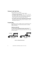
Martin Splitters also reduce signal reflections that can be a problem in larger installations or on longer cable lengths: Weak reflection with long delay. Signal OK Strong reflection with long delay. Bad signal! Weak reflection with short delay. Signal OK without Splitter Reflection with short delay. Signal OK Reflection with short delay. Signal OK with Splitter Figure 4: Eliminating data signal reflections Voltage surge protection All five out sockets on Martin Splitters are optically isolated.
Physical installation Mounting in a rig Both the DMX 5.3 Splitter and the RDM 5.5 Splitter can be flown in a rig. To install them in a rig: 1. Fasten a suitable rigging clamp for the truss or suspension bar to the Splitter with a minimum grade 8.8 M12 bolt as shown in Figure 6. Rigging clamp Warning! The bolt thread must protrude 10 mm (0.4 in.) minimum and 25 mm (0.9 in.) maximum into the Splitter when the bolt is tight. 2. Fasten the rigging clamp securely to a truss or suspension bar. 3.
Warning! Do not fasten screws with a thread length of more than 4 mm (0.15 in.) into the ends of either Splitter. 19-inch rack mounting Both the DMX 5.3 Splitter and the RDM 5.5 Splitter can be mounted in pairs side-by-side in standard 19-inch racks. Both models have the same dimensions and mounting system. To mount in a rack: 1. Fasten two Splitters together side-by-side using the four Torx 10 M3 x 6 thread-forming attachment screws supplied with one of the Splitters as shown at B in Figure 7. 2.
AC power Warning! For protection from dangerous electric shock, the device must be grounded (earthed). The local AC power source must have both overload and ground-fault (earth fault) protection. Warning! Power socket outlets or external power switches used to supply the DMX 5.3 Splitter with power must be located near the device and easily accessible so that the device can easily be disconnected from power. In an emergency, the RDM 5.
Table 1 shows some pin identification schemes. Consult a qualified electrician if you have any doubts about proper installation. Wire (US system) Wire (EU system) Pin Marking Screw color black brown live “L” yellow or brass white blue neutral “N” silver green yellow/green ground or green Table 1: Power plug pin identification Martin RDM 5.5 Splitter The RDM 5.5 Splitter is supplied with a blue Neutrik PowerCon NAC3FCA cable-mount connector for power input.
5. Insert each of the wire ends into the appropriate terminal (see illustration on right and Table 1 above) and fasten using a small flathead screwdriver. 6. Push and insert the chuck into the housing (note that there is a raised key on the chuck to ensure that it is oriented correctly). 7. Fasten the bushing using a wrench to a torque of 2.5 Nm (1.8 lb.-ft). Terminals Illustrations in this section used by kind permission of Neutrik AG.
Data connections and setup The Martin DMX 5.3 Splitter uses 3-pin XLR and the Martin RDM 5.5 Splitter uses 5-pin XLR sockets for all data connections: in, optically isolated, optically isolated, thru and out. Pins 4 and 5 in 5-pin XLR connectors are not used by DMX or RDM signals, but if you intend to use pins 4 and 5 in the RDM 5.
The LED under the termination button lights when DMX termination is applied. Termination button Figure 8: DMX termination (5.5 Splitter illustrated) Data output The Splitter’s out 1 - out 5 sockets provide five amplified, buffered, regenerated and optically isolated outputs of the data signal present at the in socket. You can create up to 5 branches on the data link by connecting DMX cable to the Splitter’s out sockets using XLR male cable connectors.
To solve this problem, the RDM 5.5 Splitter can be used as a data signal filter. If the dmx only button is pressed in, the RDM 5.5 Splitter will remove all data signals apart from DMX from the five out sockets. Note that pressing in the dmx only button will not affect the thru socket, which will continue to relay unmodified data signals from the in socket.
Operation Status LEDs Operation can be monitored using the status LEDs on the front of the Martin Splitters: Martin DMX 5.3 Splitter The power LED lights if AC mains power is applied and the Splitter’s power supply unit is working. The signal LED on the front panel lights green if a valid data signal is present at the in socket. The err (error) LED lights red if a signal present at the in socket is faulty. The LED under the termination button lights if the Splitter’s internal DMX termination is activated.
Firmware/software uploads when using Splitters Martin products that support firmware/software uploads in .MU3 file format over the data link should accept uploads without problem when a DMX 5.3 or RDM 5.5 Splitter is present on the data link. When using an RDM 5.5 Splitter, make sure that the dmx only button is not pressed in during firmware uploads. RDM and the RDM 5.5 Splitter From 2011, information on RDM and Martin products that support it is being added to the Martin website at www.martin.
Service Warning! There are no user-serviceable parts inside the device. Refer all service apart from cleaning to Martin Professional or its authorized service agents. Installation, on-site service and maintenance can be provided worldwide by the Martin Professional Global Service organization and its approved agents, giving owners access to Martin’s expertise and product knowledge in a partnership that will ensure the highest level of performance throughout the product’s lifetime.
• A PC running a Windows version supported by the Martin Uploader application. • A Martin USB Duo™ DMX Interface Box (P/N 90703010) with its supplied cables. Firmware upload procedure To install firmware in a Splitter: 1. Start the Martin Uploader application on a PC connected to the Internet and download the splitter firmware from within the Uploader application. 2. Connect the PC to a Martin USB Duo™ DMX interface box and connect the interface box to the Splitter’s data in connector. 3.
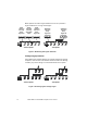
Block diagrams Martin DMX 5.3 Splitter Martin RDM 5.
Specifications Physical Depth . . . . . . . . . . . . . . . . . . . . . . . . . . . . . . . . . . . . . . . . . . . . . 125 mm (4.9 in.) Width . . . . . . . . . . . . . . . . . . . . . . . . . . . . . . . . . . . . . . . . . . . . . 220 mm (8.7 in.) Height . . . . . . . . . . . . . . . . . . . . . . . . . . . . . . . . . . . . . . . . . . . . . . 45 mm (1.8 in.) Weight . . . . . . . . . . . . . . . . . . . . . . . . . . . . . . . . . . . . . . . . . . . . . . . 0.9 kg (2 lb.) Data signal DMX (all models) .
Typical power consumption 110 V, 60 Hz . . . . . . . . . . . . . . . . . . . . . . . . . . . . . . . . . . . . . . . . . . . . . . . . . . 4 W 240 V, 50 Hz . . . . . . . . . . . . . . . . . . . . . . . . . . . . . . . . . . . . . . . . . . . . . . . . . . 4 W Measurements made at nominal voltage. Allow for a deviation of +/- 10%. Thermal Minimum ambient temperature (Ta min.) . . . . . . . . . . . . . . . . . . . -30° C (-22° F) Maximum ambient temperature (Ta max.) . . . . . . . . . . . . . . . . . .
Disposing of this product Martin Professional products are supplied in compliance with Directive 2002/96/EC of the European Parliament and of the Council of the European Union on WEEE (Waste Electrical and Electronic Equipment), as amended by Directive 2003/108/EC, where applicable. Help preserve the environment! Ensure that this product is recycled at the end of its life. Your supplier can give details of local arrangements for the disposal of Martin products.
www.martin.