Robocolor II System users guide
CONTENTS INTRODUCTION . . . . . . . . . . . . . . . . . . . . . . . . . . . . . . . . . . . . . . . . . . . . . . . . 3 INSTALLING THE ROBOCOLOR II SYSTEM . . . . . . . . . . . . . . . . . . . . . . . . . . . 3 OPERATING WITHOUT A LIGHTING CONTROLLER - STAND ALONE . . . . . . 4 OPERATING STAND ALONE IN MASTER/SLAVE MODE . . . . . . . . . . . . . . . . . . 5 OPERATING VIA A LIGHTING CONTROLLER . . . . . . . . . . . . . . . . . . . . . . . . . . 5 ADDRESS SETTING . . . . . . . . . . . . . . . . . .
WARNING! Do not attempt to operate the Robocolor II Heads without the Robocolor II Controller (e.g. plugging the Robocolor II directly into the mains outlet) as damage may occur to the units. Before attempting any of the following, ensure that the Robocolor II Controller is disconnected from the mains supply. Remove the 2 finger screws on the top-cover of each Robocolor II Head and carefully remove the covers. The lamps can now be installed in the lamp holders.
OPERATING STAND ALONE IN MASTER/SLAVE MODE If you have two or more Robocolor II Systems, this feature - Stand Alone in Master/Slave mode - allows you to operate all systems in perfect synchronisation. You must assign one, and only one, Robocolor II Systems to be master and all the rest to be slaves. Please follow the procedure listed below: On the Master System set the DIP-switch to the desired Stand Alone Sequence as described in the previous section. Remember, only one unit must be set to master.
3 4 5 6 7 unused data output socket on the unit. This plug is supplied with all Martin controllers and has a 120 Ohm resistor between pin 2 and 3 (Martin part no. 309950). If you are using more than one unit with the lighting controller then connect the data output on each unit to the data input on the following, using XLR-XLR cables.
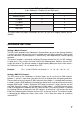
3 pin XLR to 5 pin XLR cable (3 pin Robocolor II Output to 5 pin DMX Input) Description 3 Pin female XLR (Out) 5 Pin male XLR (In) Ground (screen) 1 1 (-) signal 3 2 (+) signal 2 3 Not used 4 Not used 5 This table shows the proper connections for the 3 to 5 pin XLR adapter (Martin part no. 309163).
Example: Pin 2, 3, 7 and 8 ON will set DMX channel = 0 + 2 + 4 + 0 + 0 + 0 + 64 + 128 + 0 = 198. DIP-Switch values Switch Value Switch Value Switch Value Switch Value 1 1 4 8 7 64 10 OFF 2 2 5 16 8 128 3 4 6 32 9 256 DMX 512 PROTOCOL All features in the Robocolor II System are fully DMX implemented. When operating via DMX you can choose between two modes: Tracking (mode 1) and Vector & Tracking (mode 2).
Each DMX channel in the Robocolor II System is used to provide several different functions depending on where it is set within 0-255 increments. The functions are described in the DMX protocol listed below. If adding the DIP-switch address of the Robocolor II System to the DMX channel offset value listed for a certain function, you get the absolute DMX channel controlling that particular function.
SPECIAL DIP-SWITCH SETTINGS Description DIP-switches ON Protocol auto-detect (DMX/Martin) Stand Alone Sequence - Auto-trigger Stand Alone Sequence - Music-trigger Stand Alone Sequence - Auto-trigger (Head 1 - 4 same color) Stand Alone Sequence - Music-trigger (Head 1 - 4 same color) Color adjust pos. 1 / color adjust pos 2 (toggle with DIP-switch 1) L.E.D. Chase - Auto-trigger (for service use only) L.E.D.