
Specifications


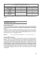


3 pin XLR to 5 pin XLR cable
(3 pin Robocolor II Output to 5 pin DMX Input)
Description 3 Pin female XLR (Out) 5 Pin male XLR (In)
Ground (screen) 1 1
(-) signal 3 2
(+) signal 2 3
Not used 4
Not used 5
This table shows the proper connections for the 3 to 5 pin XLR adapter (Martin part no.
309163).
ADDRESS SETTING
Setting a Martin Channel:
The DIP-switch located on the
Robocolor II System
allows you to set the channel, between
1 and 32, on which you want the unit to respond from the lighting controller. Please note
that the
Robocolor II System
requires 1 channel only, when operated via a Martin lighting
controller.
The channel number is selected by switching ON one or more of the first six DIP-switches.
A switch that is ON, assigns the value listed in the following table. Switches that are OFF
assign the value 0. The channel number is determined by adding the values from switch 1
to 6. Note that switch 7 to 10 should all be OFF.
Example: Pin 1, 2 and 5 ON will set channel=1+2+0+0+16+0=19.
Setting a DMX 512 Channel:
The DIP-switch on the
Robocolor II System
allows you to set the first DMX channel,
between 1 and 511, from which you want the unit to respond from the lighting controller.
Please note that the unit requires 5 DMX channels when mode 1 is selected and 6 channels
in mode 2 (see the DMX protocol in the following section which also describes how to switch
between DMX mode 1 and 2). Setting the DIP-switch to channel 1 means that the unit will
use DMX channels number 1 to 5 for operation in DMX mode 1 - the DMX channel offsets
listed in the protocol are added to the DIP-switch channel. The channel number is selected
by switching ON one or more of the ten DIP-switches. A switch that is ON assigns the value
listed in the following table. Switches that are OFF assign the value 0. The channel number
is determined by adding the values from switch 1 to 9. Note that switch 10 should be
switched OFF.
7