SynchroZap QX250 P/N 35000025 User Manual
© 1998, 1999 Martin Professional A/S, Denmark. All rights reserved. No part of this manual may be reproduced, in any form or by any means, without permission in writing from Martin Professional A/S, Denmark. Printed in Denmark. P/N 35000025, Rev.
section 1 INTRODUCTION Thank you for selecting the Martin SynchroZap QX250. This manual covers the SynchroZap QX250 with CPU software version 1.1. For the latest product news and documentation, please contact your dealer or the Martin web site at http://www.martin.dk. SynchroZap QX250 safety information WARNING! This product is for professional use only. It is not for household use.
To p r o t e c t y o u r s e l f a n d o t h e r s f r o m b u r n s a n d f i r e • Never attempt to bypass the thermostatic switch or fuses. Always replace defective fuses with ones of the specified type and rating. • Keep all combustible materials (for example fabric, wood, paper) at least 0.1 meters (4 inches) away from the fixture. Keep flammable materials well away from the fixture. • Do not illuminate surfaces within 0.3 meters (12 inches) of the fixture. • Provide a minimum clearance of 0.
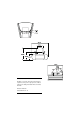
section 2 SETUP This section describes the steps required to prepare the SynchroZap for operation. bracket DIP switch data output tilt lock (2) data input S/N label lamp adjustment screw (3) mains input lamp assembly fuse holder access plate screw (2) Figure 1: Rear view Unpacking The SynchroZap QX250 comes with: • 5-meter, 3-pin shielded XLR control cable • 1.
WA R N I N G ! Disconnect the fixture from AC power before proceeding. The lamp operates under high temperature and pressure and can explode when hot. Always allow a hot lamp to cool for at least 5 minutes before removing it from the fixture and wear safety goggles to protect your eyes. 1. Remove the 2 lamp access screws from the lamp assembly and gently remove the assembly. See Figure 1. 2. Remove the old lamp, if any, by its ceramic base. 3.
Ch e ck vol tag e a nd fre qu en cy s e tti ng s Verify that the settings printed on the S/N label match your local power supply. If the voltage is not within 5 percent of the local supply, or if the frequency (50/60 Hz) is different, then the ballast and/or transformer must be rewired by a qualified technician before power is applied. Please contact your Martin dealer. Prepare the power cable The SynchroZap QX250 has a 3-pin IEC power inlet.
1. Verify that the structure can support at least 10 times the weight of all installed fixtures, clamps, cables, auxiliary equipment, etc. 2. If hanging the fixture with a rigging clamp, verify that the clamp is undamaged and is designed for the fixture’s weight. Bolt the clamp securely to the bracket with a grade 8.8 (minimum) M12 bolt and lock nut, or as recommended by the clamp manufacturer, through the clamp hole in the mounting bracket. 3.
1. Connect controller: For a DMX controller with 5-pin output, use a cable with a 5-pin male and a 3-pin female connector, such as P/N 11820005. Pins 4 and 5 are not used. For a DMX controller with 3-pin output, use a cable with 3-pin male and female connectors such as the one supplied. Connect the cable to the controller’s DMX output and the SynchroZap’s data input. 2. Connect additional fixtures: Connect the output of the fixture closest to the controller to the input of the next fixture.
For independent control, each fixture must have its own address as in example 1. If independent control is not required, 2 or more SynchroZaps may share the same address: they will receive the same instructions and behave identically. In example 2, units 1 and 2 will behave the same, as will units 3 and 4.
section 3 OPERATION Stand-alone operation The SynchroZap QX250 may be operated without a controller in a stand-alone mode in which it performs a random sequence triggered by the beat of the music. Two or more SynchroZap QX250s may be connected for synchronized stand-alone “master/slave” operation. Single SynchroZap With the fixture off, set DIP-switch pins 1,2, and 10 to ON and set the others to OFF. 2. Apply power to the SynchroZap QX250. Adjust the volume of the music until the fixture responds.
3. Apply power to the SynchroZap. After it resets it is ready to respond to the controller. The DMX protocol beginning on page 18 describes in detail how the fixture responds to DMX commands. Loss of DMX If the DMX signal is lost, the SynchroZap automatically executes a random sequence using the music trigger after 5 seconds. DMX control resumes when the signal returns.
Channels 4 and 5: mirror drums The SynchroZap has 2 asymmetrically mounted mirror drums with independently controllable rotation. Each drum can rotate in both directions at varying speeds, stand still, or be set for musically triggered random or synchronized action. Channel 4 controls the left drum and channel 5 controls the right drum.
section 4 BASIC SERVICE Replacing the lamp WARNING The lamp operates under high temperature and pressure and can explode. Always wear safety goggles to protect your eyes and allow a hot lamp to cool for at least 5 minutes before removing it from the fixture. Discharge lamps become more difficult to strike with age. If the lamp is difficult to strike, it probably needs to be replaced. You can expect, on average, to get 2000 hours of use from MSD lamps.
4. Wait for the lamp to reach full brightness. Position the fixture so the light shines on a flat, white surface. 5. If there is an off-center “hot spot,” the lamp is not centered in the reflector. Pull the hot spot into the center of the field with small adjustments of one or more of the lamp-adjustment screws. 6. If the light is significantly brighter in the center of the field than it is at the edge, the lamp is too far forward in the reflector.
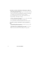
Ad j us ti ng E U m od e l vol tag e se tt in gs Local AC Supply Transformer Ballast Freq. Voltage Setting Terminal Setting Terminal 50 Hz 220 - 235 V 225 V 3 230 V 230 50 Hz 235 - 245 V 240 V 4 240 V 240 50 Hz 245 - 260 V 240 V 4 250 V 250 Transformer Ballast 225 V 240 V 230 V 240 V 250 V Figure 4: EU model transformer and ballast taps 16 1. Disconnect the fixture from AC power and place it upside down on a work table.
Ad j us ti ng U S m od e l vol tag e se tt in gs Local AC Voltage Transformer Setting 95 - 105 V 100 V, 50/60 Hz 105 - 115 V 110 V, 50/60 Hz 115 - 125 V 120 V, 50/60 Hz 215 - 235 V 225 V, 50/60 Hz Ballast Transformer 225 V 120 V 110 V 100 V 225 V / 60 Hz 225 V / 50 Hz Figure 5: US model transformer and ballast taps 1. Disconnect the fixture from AC power and place it upside down on a work table. If the lamp is hot, allow it to cool for 5 minutes and wear safety goggles to protect your eyes.
appendix a DMX 512 PROTOCOL 6-chan nel DMX protocol Channel 1 2 18 DMX Values Percent 0 - 10 11 - 19 20 - 39 40 - 100 101 - 109 110 - 130 131 - 180 181 - 239 240 - 248 249 - 255 0-3 4-7 8 - 15 16 - 39 40 - 43 44 - 51 52 - 71 72 - 94 95 - 97 98 - 100 0-8 9 - 17 18 - 26 27 - 35 36 - 44 45 - 53 54 - 62 63 - 71 72 - 80 81 - 89 90 - 98 99 - 107 108 - 116 117 - 125 126 - 134 135 - 143 144 - 152 153 - 161 162 - 170 171 - 179 180 - 187 188 - 237 238 - 248 249 - 255 0-3 4-7 8 - 10 11 - 14 15 - 17 18 - 21 2
Channel 3 4 5 6 DMX Values Percent Effect 0-8 9 - 17 18 - 26 27 - 35 36 - 44 45 - 53 54 - 62 63 - 71 72 - 80 81 - 89 90 - 98 99 - 107 108 - 116 117 - 125 126 - 134 135 - 143 144 - 152 153 - 161 162 - 170 171 - 179 180 - 187 188 - 237 238 - 248 249 - 255 0-3 4-7 8 - 10 11 - 14 15 - 17 18 - 21 22 - 24 25 - 28 29 - 31 32 - 35 36 - 38 39 - 42 43 - 45 46 - 49 50 - 53 54 - 56 57 - 60 61 - 63 64 - 67 68 - 70 71 - 73 74 - 93 94 - 97 98 - 100 Gobos Open Gobo 1 Gobo 2 Gobo 3 Gobo 4 Gobo 5 Gobo 6 Gobo 7 Gobo
1-chan nel DMX protocol Channel 1 20 DMX Values 0 - 50 51 - 101 102 - 152 153 - 255 Percent 0 - 19 20 - 39 40 - 59 60 - 100 Effect Random sequence Blackout 2.0 second trigger 1.0 second trigger 0.
appendix b SPECIFICATIONS Measurements • • Dimensions w/o bracket (LxWxH): ........... 372 x 405 x 190 mm (14.6 x 15.9 x 7.5 in) Weight with bracket but no clamp: ..........................................................11.4 kg (25 lb) Electrical, EU model • • • • • Power, current consumption at 230 V, 50 Hz with MSD 250/2: ............. 300 W, 1.51 A Power factor at 230 V, 50 Hz with MSD 250/2 ....................................................... 0.87 Ballast taps:...................................
Construction • • Housing............................................................................................ aluminum and steel Finish ................................................................................. electrostatic powder coating Thermal • Maximum ambient temperature (Ta) .......................................................40° C (104° F) • Surface temperature under normal operating conditions.........................65° C (150° F) Accessories • • Half-coupler clamp ........
appendix c D I P - S W I T C H TA B L E This table shows DIP-switch settings for channels 1- 511. Note: Pin 10 is always OFF in the 6-channel DMX mode. Pins 9 and 10 must be switched ON to select the 1-channel DMX mode. In this mode, pins 1 - 8 are used to select any channel up to 255. To find a setting, locate the channel in the table. Follow the row to the left to find the settings for pins 1 through 5; follow the column to the top to find the settings for pins 6 through 9.
SynchroZap QX250 6-Channel DMX Protocol &K1# 58 %22 #4 83 #5 ZKLWH OLJKW# JUHHQ 58 #7 6 7 2 3 #8 6 7 2 3 *#4 *#5 43 \HOORZ *#7 *#8 73 PDJH QWD OLJKW# EOXH :8 *#9 *#: 53 *#; 433 *#< 58 83 RII 63 83 533 93 EOXH 458 :3 GHHS# RUDQJH 483 73 83 :8 433 4:8 533 63 :8 73 558 4:8 93 07 <3 558 583 PXVLF#WULJJHU ;3 <3 0XVLF#WULJJHU#VSHHG# 5:3ƒ#RIIVHW VORZ 433 458 483 PHGLXP 4:8 533 IDVW 558 583 -#6HW#FK1#5#WR#JUHHQ#DQG#FK1#6#WR#JRER#<#WR#HQDEOH#ODPS#RII#