
User`s manual

22 Controls
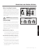
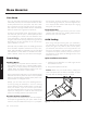
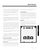
Level Knob (fig. 1)
Setting the level too high will cause the bass to seem bloat-
ed and is the single most common cause of bad sounding
subwoofers. A rule of thumb is that the subwoofer should
not draw attention to itself, but should simply make the sys-
tems low end seem more extended and accurate.
Low Pass Filter Knob (fig. 1)
When the subwoofer is connected in multi-channel mode
(via LFE), the crossover switch should be set to 'Bypass'
so that the low pass filter is not active and your processor
handles the bass management.
When connected in 2-channel mode (via left/right input),
as a general rule the low pass filter should be set equal
to approximately 70% of your speaker’s lowest frequency
response. Remember, this is a general rule. We advise
that once you try the recommended setting using the for-
mula above, you should try the surrounding settings to see
which sounds best.
Phase Control Knob (fig. 1)
The phase control is entirely dependent on the size and
configuration of your listening environment, the placement
of the unit, and your seating arrangement. Due to the way
bass sound waves develop in different rooms, there is
no rule of thumb for setting phase. For instance, if your
room has a peak at the subwoofer crossover area, you
may wish to set the phase so the actual acoustic outputs
of the subwoofer and main speakers are out of phase.
Experiment, try different settings and be patient.
Status LED (fig. 1)
When the status LED is blue, the subwoofer is on. The LED
will be off when in standby or unplugged.
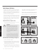
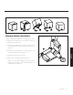
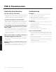
Power Mode and Trigger Input (fig. 2)
When set to 'Auto' the subwoofer will turn itself on when
detecting an audio signal. After several minutes of inactiv-
ity the subwoofer will put itself in standby mode.
If you have an external source component (such as a
receiver) with built in trigger controls, you may wish to
turn the subwoofer on and off with this source. Connect a
cable from the control component to your subwoofer and
set this switch to 'Trigger'. Although this technology is com-
monly referred to as a 12V trigger, the Dynamo 1500X
will respond to any signal between 5–24V DC.
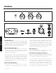
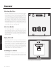
Controls
Figure 1. Dynamo 1500X controls.
Figure 2. Dynamo 1500X controls and connections.
English