STATEMENT s e t u p m a n u a l TM E2 MA R T I N LOGA N® the loudspeaker technology company
CONTENTS Contents . . . . . . . . . . . . . . . . . . . . . . . . . . . . . . . . . . . . .2 Before You Begin . . . . . . . . . . . . . . . . . . . . . . . . . . . . . .3 Master Packing List Required Tools Unpacking the Statement e2 Speaker Placement . . . . . . . . . . . . . . . . . . . . . . . . . . . .4 Initial Speaker Placement The Wall Behind the Listener The Wall Behind the Speakers The Side Walls Assembly . . . . . . . . . . . . . . . . . . . . . . . . . . . . . . . . . . . . .
BEFORE YOU BEGIN Master Packing List Before you being setting up the Statement e2, please make sure that all 15 crates/boxes are present and accounted for. The list below gives a detailed description of what can be found in each numbered crate/box.
SPEAKER PLACEMENT Initial Speaker Placement For optimal performance of the Statement e2 system we recommend that the ESL/Transition towers be placed approximately five to seven feet from the front wall (the wall in front of the listening position) and at least two feet from the side walls. The subwoofer towers should be placed diagonally (or against a wall) in the front corners of the room with at least one foot of clearance between the woofers and the walls.
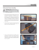
ASSEMBLY Subwoofer Tower Assembly WARNING! Assembling the Statement e2 requires two people, except for step 12 of the subwoofer tower assembly, which requires three people. Do not attempt any part of the assembly process with one person. 1 2 Place the primary subwoofer module in position on the floor, (the primary module has 10 binding posts).
4 After the second module is in position atop the primary module, place a level on it as shown. Level the module front to back by inserting a small allen wrench (or other suitable instrument) through the hole in the cones on the base of the module (detail), and rotating the cone up or down to achieve level. 5 Level the module left to right with the level in position as shown. Adjust the cone feet for height. 6 Once the secondary module is level, install the stainless steel Martin-Logan logo plates.
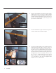
Stack the next secondary module atop the second utilizing the same assembly procedure used in step 3. Figure 8 8 Align the cones to the indentations on the cabinet below, and level the module front-to-back and left-toright, following the same procedure used in steps 4 and 5. Figure 9 9 Repeat the procedure in step 6.
10 Place the fourth and final module in position (repeating steps 3 thru 6). The top module is distinguished from the other modules by the lack of mounting holes on the top bracket (as shown). Figure 11 11 Align the slots on the top and bottom of the grill cloth frames with the curved extrusion on the module. Place firmly into position so that the velcro fasteners are securely meshed.
12 Install woofer wiring harness as shown. You can move the tower to the preferred listening position by shifting the unit from side to side and “walking” it. Figure 13 13 When you are confident the sub tower is correctly positioned, mark the floor with masking tape at each corner. Install the spikes by using a safe dolly to tip the sub tower back, remove the glides, and then screw the spikes into place. Make sure you thread the large black rubber washer onto the spike post before installing in the tower.
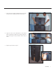
Transition/Electrostatic Tower Assembly Note: The following instructions describe the assembly of the right channel high-and mid-frequency tower. Duplicate all assembly instructions for the left tower assembly. 1 Attach the outside (semi-circle shaped) trim rail to the transition tower by aligning the five pins on the trim rail with the 5 cam holes in the tower. 2 Use a phillips head screwdriver to rotate the cams a little over 180° counter clockwise once the pin is properly aligned in the cam.
4 Install the inside wing (wedge shaped with pins on the side) trim rail by aligning the 5 pins with the corresponding cams as in the previous assembly, only this time the cams turn clockwise to lock in the trim wing. Figure 18 5 Finished transition tower assembly.
6 Pick up the transition tower assembly and insert it as shown into the base so the three holes in the mounting bracket line up with the holes in the tower. 7 Push the tower towards the center for proper alignment. 8 Once the holes are properly aligned, insert the 31/2” x 9/16” hex head lag screws through a steel washer and into the tower. Finger tighten—do not tighten all the way.
9 Use a level to bring the tower 90 degrees vertical left to right. Figure 23 10 When the tower is perfectly plumb, go ahead and tighten the bolts securely. Figure 24 11 Use your level to plumb the tower front to back.
12 Tighten tower wing bolt. Figure 26 13 Tighten base bolts. Figure 27 14 Connect the tower as shown (red to red, black to black).
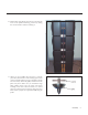
Install the ESL wing trim (wedge shaped with pins on the narrow end) by aligning the 5 pins with the corresponding cams. The cams turn clockwise to lock the trim with in place. Figure 29 16 Insert the electrostatic panel as shown. Figure 30 17 Line up holes and insert the 21/4” x 9/16” button head cap screws (black) through a steel washer and into the tower. Finger tighten.
18 Use a level to plumb the electrostatic panel left-toright. Figure 32 19 Measure the space between towers (top and bottom). The space should measure exactly 2 inches. Figure 33 20 Tighten frame bolts as shown.
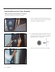
21 Use a level to plumb the electrostatic panel front-toback. Figure 35 22 Tighten wing bolts. Figure 36 23 Tighten base bolts.
24 Connect light bar Figure 38 25 Connect electrostatic panel wires to the color-coded screw-terminal connector. Figure 39 26 ESL panel properly connected.
27 Find the loops at the top of the transition tower grill sock. Figure 41 28 Hook the loops as indicated at the top of the tower. Figure 42 29 Hook the loops on the bottom of the sock on the bottom of the tower as indicated.
30 Push the grill sock into the slot provided to stretch the cloth taut, from top to bottom. Figure 44 31 Place the top of the base into position. Note: You may want to wait before installing the top of the base as settings inside the base may need changing.
CONNECTIONS—EXOS CROSSOVER INPUTS Connect the outputs of the Preamplifier/Processor to the inputs of the EXOS using either balanced or single ended connections. There are right channel, left channel and optional 0.1 effects channel inputs. WARNING! Use either all balanced or all single ended connections for signal inputs. Do not use both. Figure 46. EXOS signal inputs. Balanced connection shown.
CONNECTIONS—EXOS CROSSOVER OUTPUTS Subwoofer Outputs Connect the EXOS subwoofer outputs to the amplifier(s) for the woofer towers using either balanced or single ended connections. Both the balanced and single ended outputs are always on—you can use either option to connect the woofer tower amplifier(s) regardless of which you used for signal input. EXOS E 2 Note: Use either all balanced or all single ended connections for subwoofer outputs. Do not use both. Figure 47. EXOS outputs.
CONNECTIONS—ESL/TRANSITION TOWERS Bi-Wire Connection This method of connection uses individual runs of speaker wire from your amplifier. This doubles the signal carrying conductors from the amplifier to the speaker, thus directcoupling each portion of the crossover to the amplifier. Connect one set of wires to the upper set of binding posts which connect to the ESL panel of the Statement e2. Then connect a second set of wires to the lower binding posts which connect to the transitions tower.
Vertical Passive Bi-Amplification The very nature of vertical bi-amping dictates that both amplifiers be identical. With vertical bi-amping, each of the stereo amplifiers is dedicated to one speaker. For instance, the left channel of each amplifier drives the low pass (Transition) section while the right channel drives the high pass (ESL) section. Starting with one speaker, connect the right channel to the lower binding posts and the left channel to the upper binding posts.
CONNECTIONS—SUBWOOFER TOWERS 8-Ohm Connection 4-Ohm/Bi-Amp Connection This connection method is safe for all amplifiers (see figure 51). Use this connection method if you wish to use two amplifiers to drive the subwoofer towers (see figure 53). 2-Ohm Connection This connection is the loudest, but draws the most power from the amplifier (see figure 52). If using this connection method, make sure your amp can handle 2-Ohms. Figure 51. 8-Ohm configuration. One channel shown. Figure 52.
PASSIVE HIGH-PASS SETTINGS The High-Pass Settings The passive high-pass settings can be adjusted by changing the red and black jumpers found in the high-pass section of the ESL/Transition tower passive crossover. WARNING! Before changing the passive-high pass options be sure to turn the amps off and unplug the Statement e2 ESL/Transition tower. The design of these jumpers accommodates different listening distances to the speaker (distance between listener and speaker). The unit is shipped in 15ft mode.
Figure 56. Open (not connected) jumpers. Figure 57. Closed (connected) jumpers. Figure 58. Jumper settings for 10-foot mode. Figure 59. Jumper settings for all-closed mode. Figure 60. Jumper settings for all-open mode. Figure 61. Jumper settings for 15-foot mode.
AC POWER CONNECTIONS Because your MartinLogan Statement e2 ESL/Transition towers use an internal power supply to energize their electrostatic cells with high-voltage DC, they must be connected to an AC power source. The EXOS crossover must also be connected to an AC power source. For this reason the proper IEC standard power cords are provided.
MAKING IT WORK TOGETHER Making It Work Together (Part 1) Setting the Dip Switches Now that you know all the connection options and how to set them, it’s time to make the speakers work in their target environment. For this part, it is recommended that an audio analyzer be used (RTA or a computer based instrument). This should only be done by a qualified technician. Start with default settings. Look at the 200Hz to 500Hz area of the ESL-transition tower alone.
Making It All Work Together (Part 2) You will need to set the dip switches for both right and left channel. Note: Only one dip switch per dip switch cluster should be on at a time. Note: This unit will generate electrical transients on its outputs when the power is turned off or on. This can cause loud noises if the amplifiers are turned on. 5 If available, use test equipment to optimize the subwoofer response. 6 The 50Hz control works the same as the 25Hz control.
Speaker Placement (Fine Tuning) Toe in the ESL/Transition towers so the listener is looking at the inner 1/ 3 of the ESL panels. Sitting at the listening position, hold a flashlight under your chin and point it at each speaker. The reflection of the flashlight should be 1/ 3 of the way out from the inner edge of the panel (see figure 68). Viewed from the listening position, the 2-inch space between the transition tower and ESL frame should appear the same on both channels (see figure 66).
MA R T I N LOGA N® the loudspeaker technology company 2101 Delaware Street, Lawrence, Kansas 66046, USA tel 785.749.0133 fax 785.749.5320 www.martinlogan.com ©2003 MartinLogan, All rights reserved Rev.