MAC 500/E user manual
© 1997 - 2000 Martin Professional A/S, Denmark. All rights reserved. No part of this manual may be reproduced, in any form or by any means, without permission in writing from Martin Professional A/S, Denmark. Printed in Denmark. P/N 35000016, Rev.
section 1 Introduction MAC 500/E safety information................................................................................................... ................................................. 4 section 2 Setup Unpacking .................................................................................................................................................................................... 5 Installing or changing the lamp...................................................................
section 1 INTRODUCTION Thank you for purchasing the MAC 500/E moving-head spotlight from Martin. Every detail of its construction and programming is designed to make the MAC 500/E extremely bright, quiet and reliable. With proper setup and maintenance, it will provide years of trouble-free operation. This manual covers the MAC 500 with magnetic ballast and the MAC 500 E with electronic ballast. “MAC 500/E” refers to both models when describing common features and procedures.
section 2 SETUP This section describes the steps required to prepare the MAC 500/E for operation. Unpacking The MAC 500/E package includes: • • • • • 2 Fast-Lock clamp brackets 5-meter XLR-XLR control cable User manual 7 extra gobos 1 spare rotating gobo spring The packing material is carefully designed to protect the fixture during shipment - always use it or a custom MAC 500/ 600 flight case to transport the fixture.
. Before turning the lamp on, reset the RL AH and RL ST counters. See “Readouts” on page 14. Powering the fixture WARNING! For protection from dangerous electric shock, the fixture must be grounded (earthed). The AC mains supply shall be fitted with a fuse or circuit breaker and ground-fault protection.
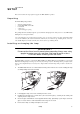
safety wire attachment point arrow points to front (neutral pan) 5. Working from a stable platform, hang the fixture on the truss. The front of the fixture is indicated by the arrow on the base. 6. Install a safety wire that can bear at least 10 times the weight of the fixture. The attachment point is designed to fit a caribiner clamp. Never use the carrying handles for secondary attachment. 7. Tighten the rigging clamps securely to the structure. 8.
1. Connect the controller’s data output to the MAC 500/E’s data input. For a • 2. 3. 8 DMX controller with 5-pin output: use a cable with 5-pin male and 3-pin female connectors such as P/N 11820005. Pins 4 and 5 are not used. • DMX controller with 3-pin output: use a cable with 3-pin male and female connectors such as the one supplied. • Martin RS-485 Protocol controller: use a phase-reversing cable, such as P/N 11820006, with 3pin male and female connectors or reconfigure the XLR output.
section 3 OPERATION This section describes the MAC 500/E’s controllable effects and the options for customizing them for your application. Option selection is described in the next section. Martin RS-485 control The MAC 500/E may be controlled with the Martin 3032 controller with version 2.04 or later software.
Controllable effects All moving effects are reset to a “home” position when the fixture is powered up. The fixture can also be reset via DMX if DMX reset (SPEC /dR ES ) is enabled. There is also a combination of DMX values that allows you to reset the MAC 500/E even if this feature is disabled; see the DMX protocol for details. An on-the-fly position correction system monitors the position of the color wheels, fixed-gobo wheel, and rotating gobos.
The Shortcuts (SP EC/ SCUT ) setting determines whether the gobo wheel takes the shortest path to the next position or turns in one direction only. The setting may be overridden on the speed channel in vector mode. Rotating gobos The MAC 500/E has 5 rotating positions for glass or metal gobos. Gobos may be rotated in both directions at varying speeds or indexed to any position. The function and gobo are selected on channel 5 and the velocity or index position are selected on channel 6.
section 4 CONTROL PANEL The 4-digit LED control panel on the front of the MAC 500/E allows you to set the address and personalities, read lamp hours and other information, calibrate effects, control the fixture manually, and run stand-alone tests and demo programs. Most of these functions may be performed remotely via the serial link with the MPBB1 Uploader The display can be flipped for easy reading by pressing the [↑] and [↓] keys simultaneously.
Personality settings Personality Pan/tilt speed Pan/tilt swap Pan inverse Tilt inverse Fixture type Display on/off Path Dimmer mode Pan/tilt feedback Effects feedback Iris reflection reduction Normal pan and tilt control ON Reverse DMX pan control, right O FF Normal pan control, left O FF P RIS Operate with rotating prism F ROS Operate with optional variable frost ON Display stays on O FF Display goes out 2 minutes after last key press 10 - 100 Adjust display intensity ON Enable D
Address and protocol selection One of the operating modes shown below must be selected. Factors to consider when selecting a mode will depend on your controller and are discussed in the previous section. Maximum flexibility is provided in mode 4. Each fixture must be assigned its own channels to receive instructions from the controller. The address, also known as the start channel, is the first channel used. Addresses are independent of the physical link: they may be set in any convenient order.
4. Press the [MENU] and [↓] keys at the same time and hold them for 3 seconds until “25” shows in the display. 5. Press the [↑] and [↓] keys until the display shows the temperature measured. 6. Press [ENTER] to save the setting.
Utilities Calibration (CAL) The calibration menu allows you to adjust the effects to achieve total uniformity between fixtures: it is not a substitute for mechanical adjustment. Select dimmer/shutter (d OF ), color wheels (C1 OF, C2 OF ), rotating-gobo wheel (RGO F ), fixed-gobo wheel (FG OF ), or focus (FOO F ) and adjust the effect’s offset with the arrow keys. Offsets are adjustable from 1 to 255 for all effects except the fixed-gobo wheel, which is adjustable from 127 to 129.
section 5 GOBOS AND COLOR FILTERS The MAC 500/E has 5 rotating positions for glass or metal gobos, 9 static positions for metal gobos, and 9 positions for interchangeable dichroic glass color filters in special holders. This section describes how to replace these items. Gobo specifications For best results, MAC 500/E gobos should meet the following specifications. Glass gobos • • • • • Coating: .................................................................................................
Metal and image gobos The metal gobos supplied with the MAC 500/E may be used in either wheel. They are black on one side to reduce reflections; the black side must face out, away from the lamp. For correct projection of text and images, the side with the true image must be installed facing in, towards the lamp.
Changing rotating gobos WARNING! Disconnect the fixture from AC power before removing any cover. Without tools 1. Remove the top head cover as described under “Accessing parts” on page 21. 2. Turn the gobo wheel until the easiest access to the desired gobo position is obtained. Turn the color wheel until the open position is over the gobo position. 3. Tilt the head so the lens points down. Push the gobo and retaining spring out of the back of the holder.
Default color filter positions Color wheel 1 Wheel as seen from front, in open position. 1 2 3 4 5 6 7 8 9 Blue 111 Red 301 Magenta 507 Green 202 Yellow 604 Purple 502 Blue 101 Pink 312 Cyan 401 62327015 62327021 62327023 62327018 62327019 62327025 62327016 62327022 62327017 Changing color filters WARNING! Disconnect the fixture from AC power before removing any cover. 20 1. Remove the top head cover as described under “Accessing parts” on page 21. 2.
section 6 MAINTENANCE AND BASIC SERVICE The MAC 500/E operates under challenging conditions presented by heat, humidity, dust, and touring. It requires regular cleaning and lubrication to keep performing at its peak. The maintenance schedule will depend heavily on the application and should be discussed with your Martin technician. This section describes basic maintenance. Refer any service procedure not described here to a qualified technician.
Replacing fuses The MAC 500/E has 4 fuses. The main fuse is located on the power-switch panel and may be replaced without opening the fixture. The fuses for each of the 3 low-voltage power supplies are located on the printed circuit board. If one of the circuit board LEDs does not light, one of these fuses may be blown. 1. Remove the printed circuit board. 2. Locate and replace the defective fuse with one of the same rating.
MAC 500 E with electronic ballast Electronic ballast models that come factory set for 100 V or 120 V have a 10 A main fuse, which is located near the power switch. Units set at 210 V and above have a 6.3 A main fuse. Use a 6.3 A fuse when the WUDQVIRUPHU is set at 200, 210, 220, 230, or 240 V. Use a 10 A time-delay fuse when it is set at 100, 110, or 120 V. No rewiring of the electronic EDOODVW is necessary; it works at any voltage between 100 and 250 volts, and at any frequency between 50 and 60 Hz.
If there is no functional software in memory, the fixture must be set to boot mode manually before starting the upload. If the control panel works, select UPLd from the SPEC menu and confirm when SURE is displayed by pressing [ENTER]. If the control panel does not work, boot mode can be engaged by moving jumper PL121 on the main circuit board to pins 1 and 2 as follows. PIN 1 È PIN 1 È PL121 PL121 normal setting hard boot setting 1. Remove the printed circuit board.
Optimizing lamp alignment The lamp alignment is set at the factory. If, the light distribution is uneven, lamp alignment may be adjusted as follows. A 3 mm Allen wrench is required. 1. Disconnect the fixture from AC power supply and allow the lamp to cool for 15 minutes. 2. Make a preliminary adjustment: remove the lamp assembly and turn the 3 lamp adjustment screws to position the lamp-socket plate a distance of 38 mm (1.5”) from the access plate (outside measurement) as shown.
Cleaning Optical components Be very careful when cleaning the optical components. The colored surface on the dichroic filters is achieved by means of special multi-layer coatings and even small scratches may be visible. Residues from cleaning fluids can bake onto components and ruin them. 1. Allow the components to cool completely. 2. Wash dirty lenses and filters with isopropyl alcohol. A generous amount of regular glass cleaner may also be used, but no residues may remain. 3.
section 7 APPENDICES DMX protocol DMX Channel DMX1 DMX2 DMX3 Start code = 0 DMX4 Value Percent Function Shutter, Strobe, Reset, Lamp On/Off 1 1 If DMX reset is disabled, a reset command may be sent if color wheel 1 set to cyan 401(144-148) and color wheel 2 is set to red 308 (157-160). 2 If DMX lamp off is disabled, a lamp off command may be sent if color wheel 1 is set to cyan 401 (144-148) and color wheel 2 is set to red 308 (157-160).
DMX Channel DMX1 DMX2 DMX3 Start code = 0 DMX4 Value Percent Function COLOR 2: Normal Functions 4 0 - 16 16 - 32 32 - 48 48 - 64 64 - 80 80 - 96 96 - 112 112 -128 128 - 144 0-6 6 - 13 13 - 19 19 - 25 25 - 31 31 - 38 38 - 44 44 - 50 50 - 56 Color Scroll White CTC 3200-4100 CTC 3200-5600 CTC 3200-4100 Blue 104 CTC 3200-5600 Blue 108 Blue 104 Green 206 Blue 108 Red 308 Green 206 Yellow 603 Red 308 CTC 5500-2900 Yellow 603 CTC 5500-4200 CTC 5500-2900 145 - 148 149 - 152 153 - 156 157 - 160 161 - 164
DMX Channel DMX1 DMX2 DMX3 Start code = 0 DMX4 Value Percent Function Fixed Gobos 7 Gobo mode = fixed (default) 7 Gobo mode = scroll (optional) 8 9 0-9 10 - 19 20 - 29 30 - 39 40 - 49 50 - 59 60 - 69 70 - 79 80 - 89 90 - 102 0-4 4-8 8 - 11 12 - 15 16 - 19 20 - 23 24 - 27 27 - 31 31 - 35 35 - 40 Fixed gobo positions Open gobo Gobo 1 Gobo 2 Gobo 3 Gobo 4 Gobo 5 Gobo 6 Gobo 7 Gobo 8 Gobo 9 103 - 119 120 - 136 137 - 153 154 - 170 171 - 187 188 - 204 205 - 221 222 - 238 239 - 255 40 - 47 47 - 53 5
DMX Channel DMX1 DMX2 DMX3 Start code = 0 DMX4 Value Percent 0 - 19 20 - 79 80 - 89 90 - 149 150 - 215 0-7 8 - 31 31 - 35 35 - 58 59 - 84 Prism Prism off Rotating prism, CCW fast No rotation Rotating prism, CW slow Prism off 216 - 220 221 - 225 226 - 230 231 - 235 236 - 240 241 - 245 246 - 250 251 - 255 84 - 86 87 - 88 89 - 90 91 - 92 93 - 94 95 - 96 96 - 98 98 - 100 Combined Rotating Prism and Gobo Macros Macro 1 Macro 2 Macro 3 Macro 4 Macro 5 Macro 6 Macro 7 Macro 8 0 - 255 0 - 100 Variable
Messages Display readout Appears if... What to do ... automatic protocol detection is enabled but the protocol (Martin/DMX) cannot be determined because there is no control data. • Verify that the controller is sending and the serial link is properly connected. LER R (Lamp error) ... the lamp doesn’t ignite within 10 minutes of receiving the ‘Lamp ON’ command. Likely reasons are a missing or defective lamp, or insufficient AC voltage.
Tr o u b l e s h o o t i n g Problem One or more of the fixtures is completely dead. Fixtures reset correctly but all respond erratically or not at all to the controller. Probable cause(s) Remedy No power to fixture. Check that power is switched on and cables are plugged in. Primary fuse blown (located at the mains inlet cable). Disconnect fixture and replace fuse. Secondary fuse(s) blown (located on PCB inside base). Disconnect fixture. Check fuses on PCB and replace.
Circuit board layout CONTROL MODULE MAINS IN TILT FEEDBACK MAINS OUT (TO BALLAST IN) LAMP FEEDBACK PAN FEEDBACK MAGNETIC SENSORS FAN (HEAD) + TEMP SENSE FAN (BASE) PAN/TILT INDEX SWITCES GOBO 2 HARD BOOT JUMPER PRISM ROT. PRISM FOCUS IRIS SERIAL DATA LINK GOBO 1 XLR PIN-OUT JUMPER ROT.
Specifications Measurements • • • • • Length........................................................................................................................................... 356 mm (14.0 in) Width ............................................................................................................................................ 481 mm (18.9 in) Height (head at tilt limit) ..............................................................................................................
Accessories Please see the online gobo catalog at http://www.martin.dk for additional gobos available from Martin. • • • • • • • • • • • • • Outdoor Protection Dome.......................................................................................................................... 90525010 MPBB1 Uploader ...................................................................................................................................... 90758410 MP-2 Uploader ..........................................
L 1 M ODE 2 3 4 1 2 3 I G H T C 4 9 8 optional 7 default 6 5 O L O R G O B O S E default 25 50 ← 72 75 LOW PWR (E) 80 125 O P E N 128 D IMMER fast 147 148 167 168 R ANDOM S TROBE med 150 MAC 500 DMX Protocol 100 D IMMER P ULSE opening closing ← 99 100 ← 119 175 200 225 250 245 f m s 245 246 255 R ND C OLO R CH. 4 A LT O RND PULSE O R ESET O PEN L AMP O PEN L AMP P open close P O FF * ON * slow E E > 5 sec.