VENT-FREE FIREPLACE SYSTEMS INSTALLATION AND OPERATING INSTRUCTIONS MODEL: 33ISDG Natural Gas or Propane/LPG Control Type: Milli-Volt and T-Stat WARNINGS WARNINGS If the information in this manual is not followed exactly, a fire or explosion may result causing property damage, personal injury or loss of life. This appliance may be installed in an aftermarket, permanently located, manufactured (mobile) home, where not prohibited by local codes.
CONTENTS Important Safety Information ..................................3 Checking Gas Pressure .........................................18 Product Features ......................................................5 Electrical Wiring (Milli-Volt) ...................................19 Operation ..............................................................5 Electrical Wiring (Fan)............................................21 Natural Gas ..........................................................
IMPORTANT SAFETY INFORMATION INSTALLER Please leave these instructions with the appliance. OWNER Please retain these instructions for future reference. IMPORTANT WARNING Read these instructions carefully before installing or trying to operate this vent-free gas heater. • Any change to this heater or its controls can be dangerous. • Improper installation or use of the heater can cause serious injury or death from fire, burns, explosion or carbon monoxide poisoning.
IMPORTANT SAFETY INFORMATION 17. Unvented gas heaters are a supplemental zone heater. They are not intended to be the primary heating appliance. 18. Unvented gas heaters emit moisture into the living area. In most homes of average construction, this does not pose a problem. In houses of extremely tight construction, additional mechanical ventilation is recommended. 19.
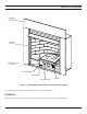
PRODUCT FEATURES Optional Face Plate Fireplace Screen Optional T-stat Sensor On/Off Switch Piezo Ignitor Control Knobs Blower Figure 1 - Unvented Gas Heater with Control Access Door Open Your vent-free fireplace must be mounted to the floor or the fireplace hearth. OPERATION This unvented gas heater requires no outside venting and burns cleanly with high heating efficiency.
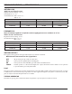
PRODUCT FEATURES AND SPECIFICATIONS NATURAL GAS Milli-Volt and T-Stat Pressure Regulator Pressure Setting: 3.5" w.c. Pilot Regulator: 3.5" w.c. Gas Inlet Pressure: Max. 10 1/2" w. c. Min. 5" w.c. Gas Rate Model Number 33ISDNTG 33ISDNVG Control Millivolt T-Stat Max BTU/HR 28,000 28,000 Min BTU/HR 19,000 19,000 PROPANE/LPG Note: An external regulator is required to reduce supply pressure to a maximum of 13" w.c. Milli-Volt and T-Stat Pressure Regulator Pressure Setting: 10" w.c. Gas Inlet Pressure: Max.
GETTING STARTED MAKE SURE YOU HAVE RECEIVED ALL PARTS Check your packing list to verify that all listed parts have been received. You should have the following: • Installation/Operating instructions • Black Louvers (5) • 33" unvented gas heater with brick panels. • Canopy • Volcanic rock and rock wool • Two (2) anchoring screws • Mounting screws for canopy • Log box (refer to installation instructions) Accessory face plates available to finish the insert.
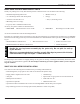
GENERAL INSTALLATION INFORMATION REMOVING SCREEN WARNING Remove fireplace screen by pushing screen frame panel up and out. See Figure 2. Do not operate the unit without the screen frame panel and canopy installed. NOTE: Fireplace screen must be removed to access log box and to install canopy. Figure 2 - Removing Fireplace Screen INSTALLING CANOPY 1. Remove the fireplace screen as described in the previous section. 2. Align canopy with the holes in the top frame assembly. See Figure 3. 3.
GENERAL INSTALLATION INFORMATION CODES Adhere to all local codes or, in their absence, the latest edition of THE NATIONAL FUEL GAS CODE ANSI Z223.1 or NFPA54 which can be obtained from… WARNING American National Standards Institute, Inc. 1430 Broadway New York, NY 10018 or National Fire Protection Association, Inc. Batterymarch Park Quincy, MA 02269 Do not install the heater … • Where curtains, furniture, clothing, or other flammable objects are less than 42" from the front of the heater.
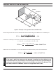
GENERAL INSTALLATION INFORMATION Counter Fireplace H W Figure 4 - Example of a Large Room with 1/2 Wall Divider The following formula can be used to determine the maximum heater rating per the definition of unconfined space: BTU/Hr = (L1 + L2) Ft x (W) Ft x (H) Ft 50 x 1000 Consider two connecting rooms with an open area between, with the following dimensions: L1 = 151/2 Ft., L2 = 12 Ft., W = 12 Ft., H = 8 Ft.
CLEARANCES AND HEIGHT REQUIREMENTS WARNING The dimensions shown in Figures 5 and 8 and defined in the fireplace manufacturer's instructions are minimum clearances to maintain when installing this heater. Left and right clearances are determined when facing the front of the heater. Follow these instructions carefully to ensure safe installation. Failure to follow instructions exactly can create a fire hazard. NOTE: Clearances are necessary to combustible surfaces only.
CLEARANCES and HEIGHT REQUIREMENTS HEAT RESISTANT MATERIAL (MINIMUM REQUIREMENTS) WITH NO WOODEN MANTEL OR OTHER COMBUSTIBLE PROJECTION Heat resistant material (minimum requirements) with wooden mantel or other combustible projection: No combustible materials To install the heater with a wooden mantel shelf or other combustible within 8” of opening. projection above, first measure the heat resistant material shown in Do not cover louvers. Figure 7.
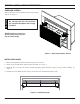
CLEARANCES and HEIGHT REQUIREMENTS The gas log heater must be installed at least 5" above any combustible flooring material, such as carpeting or tile, which is closer than 14" to the base of the fireplace. See Figure 10.
FIREPLACE FRAMING If unit is to be “built in,” fireplace framing can be built before or after the appliance is set in place. BE SURE THAT ALL PACKING MATERIAL HAS BEEN REMOVED FROM THE UNDERSIDE OF THE UNIT PRIOR TO SETTING THE FIREBOX IN PLACE. Construct fireplace framing following Figures 11 through 14. See Figure 6 on page 11 for fireplace dimensions. The framing headers may not rest directly on top of the firebox.
SECURING HEATER TO FLOOR NOTE: Clearance requirements as detailed in “Clearances and Height Requirements” section of this manual must be met before securing heater in place. To prevent movement, the heater must be secured to the floor or hearth. 1. Lift off louvers and remove the screen. 2. Remove log set. 3. To remove the grate and base assembly, take out two screws as shown in Figure 15. 4. Lift grate and base assembly out of the firebox. 5.
CONNECTING THE GAS CAUTION NOTICE: A qualified gas appliance installer must connect the heater to the gas supply. Consult all local codes. Use new black or steel pipe. Internally tinned copper or copper tubing can be used per National Fuel Code, section 2.6.3, providing gas meets hydrogen sulfide limits, and where permitted by local codes. Gas piping system must be sized to provide minimum inlet pressure (listed on Data Plate) at the maximum flow rate (BTU/Hr).
CHECK GAS TYPE: The gas supply must be the same as stated on heater's rating plate. Located behind the control access door (Figure 1, page 5). If the gas supply is different, DO NOT INSTALL the heater. Contact your dealer for the correct model. Connecting to the wrong gas type may result in property damage or personal injury. WARNING CAUTION CONNECTING THE GAS Connecting directly to an unregulated propane/L.P.G. tank can cause an explosion.
WARNING CHECKING GAS PRESSURE Connecting directly to an unregulated propane/LPG tank can cause an explosion. The stainless flex line is on the right side facing the fireplace and can connect to either a 3/8 NPT female or 1/2 NPT male pipe. To connect from the opposite side, route the pipe under the rear portion of the unit. Test all gas joints from the gas meter to the heater valve for leaks using a gas analyzer or soap and water solution after completing connection. DO NOT USE AN OPEN FLAME.
The milli-volt valve is a self-powered combination gas control THAT DOES NOT REQUIRE 110 VAC TO OPERATE. WARNING ELECTRICAL WIRING (MILLI-VOLT) Label all wires prior to disconnection when servicing controls. Wiring errors can cause improper and dangerous operation. Verify proper operation after servicing.
ELECTRICAL WIRING (MILLI-VOLT) CONNECTING REMOTE RECEIVER (Figure 21) THESE INSTRUCTIONS SUPERCEDE THE SECTION ENTITLED “HEARTH MOUNT” IN THE MILLI-VOLT HAND-HELD REMOTE INSTRUCTIONS SUPPLIED WITH THE REMOTE. 1. Remove cover on control panel to show opening for remote Remote receiver. Receiver 2. Connect the remote connectors located in the unit. 3. Slide remote receiver in the opening of control panel. Use two screws provided to attach remote receiver to the control panel. 4. Replace Cover.
This fireplace has a three-prong, grounded electrical plug. This plug helps protect you against electrical shock. Only connect plug to a properly grounded, three-prong receptacle. Do not cut or remove the grounded prong from this plug. WARNING WARNING ELECTRICAL WIRING (FAN) Never attempt to service heater while it is plugged in, operating, or hot. Burns and/or electrical shock could result. IMPORTANT: Always check local building codes.
LOG PLACEMENT WARNING Before you begin — This unit is supplied with six (6) ceramic fiber logs. Do not handle these logs with your bare hands. Always wear gloves to prevent skin irritation from ceramic fibers. After handling the logs, wash your hands gently with soap and water to remove any traces of fibers. The positioning of the logs is critical to the safe and clean operation of this heater. Sooting and other problems may result if the logs are not properly and firmly positioned in the appliance.
LOG PLACEMENT 3. Place left base log (#3) on two pins on left side of grate. See Figure 21. Left Base Log (#3) Pins Figure 21 - Installing Left Base Log (#3) Right top log (#4) 4. Place right top log (#4) on two pins located to the left of right base log. See Figure 22.
LOG PLACEMENT 5. Place right end of left top log (#5) on bottom center grate pin. Rest the left end of left top log (#5) on the left base log. See Figure 23.
LOG PLACEMENT 6. Place right front log (#6) on two pins on the right front of grate. See Figure 25. Right Front Log (#6) Right Base Log Pins Figure 25 - Installing Right Front Log (#6) PLACING ROCK WOOL After installing logs, place TPB-RW (Rock Wool) in dime-size pieces evenly across the burner surface in between the logs. Do not add additional Rock Wool. See Figure 26 Extrusions Wash hands after placing Rock Wool. Itching may occur. WARNING . • Use only TPB-RW provided with log set.
FLAME APPEARANCE Flames from the pilot, front and rear burner should be visually checked as soon as the heater is installed. In addition, periodically check the flames visually during operation. CHECKING THE PILOT FLAME The pilot flame must always be present when the heater is in operation. It should just touch the top of the thermocouple tip for natural. See Figure 31 for correct pilot flame. If the pilot flame does not touch the thermocouple, then the main burner cannot function reliably.
CHECKING THE BURNER FLAME In normal operation at full rate after 15 minutes, the following flame appearances should be observed: Glowing Embers Figure 33 - Correct Appearance of Rear Flames Burner will have a random pattern of yellow flames as shown in Figure 33. There should be glowing embers on the front burner. Note: The flames and embers will be an opaque orange color during the burn off time. OPERATING INSTRUCTIONS Avoid any drafts that alter burner flame patterns.
OPERATING INSTRUCTIONS WARNING WARNING FOR YOUR SAFETY READ BEFORE LIGHTING If you do not follow these instruction exactly, a fire or explosion may result causing property damage, personal injury or loss of life. A. This appliance is equipped with a piezo ignition device which automatically lights the pilot. If pilot is not working see Match Lighting Instructions on page 30. B. BEFORE OPERATING smell all around the appliance area for gas.
OPERATING INSTRUCTIONS MILLI-VOLT/THERMOSTAT CONTROL LIGHTING INSTRUCTIONS 1. STOP! Read the safety information label. 2. Make sure the manual shutoff valve is fully open. 3. This gas log set is equipped with an ignition device (piezo) which automatically lights the pilot. If piezo ignitor does not light the pilot, refer to instructions for “Match Lighting Instructions,” page 30. 4. Turn gas control knob clockwise to the OFF position and turn ON/OFF switch to OFF position. 5.
OPERATING INSTRUCTIONS AND BLOWER OPERATION MATCH LIGHTING INSTRUCTIONS 1. Remove any items necessary for easy access to the pilot (for example: logs, screens, etc.). 2. Follow appropriate lighting instructions found previously. Instead of pushing and releasing the piezo button, light a match and hold the flame to the end of the pilot and ignite the pilot. 3. After control knob has been released and pilot stays lit, reinstall any items that were removed for pilot access. 4.
CLEANING AND SERVICING WARNING Annual inspection and cleaning by your dealer or qualified service technician is recommended to prevent malfunction and/or sooting. Turn off heater and allow to cool before cleaning. Disconnect electrical power before cleaning or servicing. Remove logs, handling carefully by holding gently at each end. Gloves are recommended to prevent skin irritation from ceramic fibers. If skin becomes irritated, wash gently with soap and water. Refer to manual for correct log placement.
WARNING WARNING TROUBLESHOOTING Turn appliance OFF and allow to cool before servicing. Only a qualified service person should service and repair the heater. Note: All troubleshooting items are listed in order of operation. OBSERVED PROBLEM POSSIBLE CAUSE REMEDY When ignitor button is pressed, there is no spark at ODS/pilot. 1. Ignitor electrode positioned wrong. 2. Ignitor electrode is broken. 3. Ignitor electrode not connected to ignitor cable. 4. Ignitor cable pinched or wet. Keep ignitor cable dry.
WARNING TROUBLESHOOTING If the gas quality is bad, your pilot may not stay lit, the burners may produce soot and the heater may backfire when lit. If the gas quality or pressure is low, contact your local gas supplier immediately. OBSERVED PROBLEM POSSIBLE CAUSE REMEDY ODS/pilot lights, but flame goes out when control knob is released. 1. Control knob not fully pressed in. 2. Control knob not pressed in long enough. 1. Press in control knob fully. 2.
ILLUSTRATED PARTS BREAKDOWN 8 8 2 8 8 3 5 7 6 13 12 8 1 14 8 WARNING 4 34 Failure to position the parts in accordance with these diagrams or failure to use only parts specifically approved with this appliance may result in property damage or personal injury.
REPLACEMENT PARTS LIST Item Qty 1 2 3 4 5 6 7 1 1 3 1 1 1 1 Description DIS33N/P Screen Assembly Canopy Assembly Top Black Louver Bottom Black Hang On Louver Assembly Left Firebrick Right Firebrick Center Firebrick 23D8028 23D8027 23D0200K 23D8016 53D0753 53D0752 53D0751 OPTIONAL FACE PLATE 8 8 1 1 33" x 43" Black Face Plate Kit 36" x 50" Black Face Plate Kit DIFACESM DIFACELG OPTIONAL BLOWER COMPONENTS 12 13 14 23D8036 1 1 1 Fan Blower with Speed Control Blower Thermostat Wiring Harness BL
WARNING ILLUSTRATED PARTS BREAKDOWN Failure to position the parts in accordance with these diagrams or failure to use only parts specifically approved with this appliance may result in property damage or personal injury.
REPLACEMENT PARTS LIST REPLACEMENT PARTS ARE AVAILABLE THROUGH YOUR RETAILER.
ILLUSTRATED PARTS BREAKDOWN REPLACEMENT PARTS ARE AVAILABLE THROUGH YOUR RETAILER.
NOTES 23D8036 39
LIMITED LIFETIME WARRANTY POLICY The following components are warranted for life to the original owner, subject of proof of purchase: Firebox, Combustion Chamber, Heat Exchanger, Grate, and Stainless Steel Burners. FIVE YEAR WARRANTY The following components are warranted for 5 years to the original owner, subject of proof of purchase: Vent Free Ceramic Fiber Logs, Catalytic Filter and Aluminized Burners.