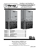
ComPac® I and ComPac® II Air Conditioner Product Manual Vertical Wall-Mount Air Conditioners with Front Control Box Panel Models AVP24-30-36-42-48-60-72 Chapter 1 Description....................................... 5 Chapter 2 Installation..................................... 18 Chapter 3 Start-Up......................................... 30 Chapter 4 Troubleshooting............................. 32 Chapter 5 Maintenance................................... 35 Chapter 6 Warranty.................................
How To Use This Manual This manual is intended to be a guide to Marvair's ComPac® line of vertical air conditioners. It contains installation, troubleshooting, maintenance, warranty, and application information. The information contained in this manual is to be used by the installer as a guide only. This manual does not supersede or circumvent any applicable national or local codes.
WARNING • If the information in these instructions are not followed exactly, a fire may result causing property damage, personal injury or loss of life. • Read all instructions carefully prior to beginning the installation. Do not begin installation if you do not understand any of the instructions. • Improper installation, adjustment, alteration, service or maintenance can cause property damage, personal injury or loss of life.
Table of Contents Chapter 5 Maintenance 5.1 Scheduled Maintenance..........................................................................................................................35 Chapter 6 Warranty 6.1 Limited Product Warranty.......................................................................................................................36 6.2 Optional Silver Service Program............................................................................................................
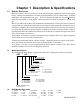
Chapter 1 Description & Specifications 1.1 General Description Marvair's ComPac® lines are a series of vertical wall-mounted air conditioning systems that provide heating, cooling, and ventilation for electronic equipment shelters, process control centers, and other applications with high internal heat gains. The series includes multiple sizes and nominal cooling capacities from 24,000 to 72,000 BTUH. Resistance heating elements are available in various wattages.
1.4 Ratings & Specifications MODEL 24 30 36 42 48 60 72 0.10 860 1100 1310 0.20 810 1000 1220 1650 1900 1900 2100 0.25 740 960 1185 1585 1830 1830 1950 0.30 670 920 1150 1520 1760 1760 1800 0.40 0.50 810 1060 1450 1700 1700 1730 1360 1620 1620 1660 Table 1.
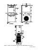
Figure 1a. ComPac® I & ComPac® II A/C Dimensions- Models AVP20-36 (in inches) Figure 1b.
Figure 1c.
1.5 General Operation Refrigerant Cycle (Cooling Mode) The ComPac® I & ComPac® II A/C use R-22 refrigerant in a conventional vapor-compression refrigeration cycle to transfer heat from air in an enclosed space to the outside. A double blower assembly blows indoor air across the evaporator. Cold liquid refrigerant passing through the evaporator is boiled into gas by heat removed from the air. The warmed refrigerant gas enters the compressor where its temperature and pressure are increased.
1.6 Electronic Control Board Mode of Operation (AVP24-72) Normal 24 VAC power must be continuously applied to “R” and “C”. Upon a call for cooling “Y” and with the high pressure switch (HPS) closed, the compressor will be energized. (Note: See the delay on make feature.) The compressor will remain energized during the 3 minute timed low pressure by-pass cycle. If the low pressure switch (LPS) is open after the 3 minute by-pass cycle, the compressor will de-energize.
Low Ambient Control The low ambient control permits cooling when outdoor ambient temperatures are low. The control uses a reverse-acting high pressure switch to cycle the condenser fan motor according to liquid refrigerant pressure conditions. Switch closure and fan operation occurs when the pressure reaches 250 PSIG. The switch opens again when the refrigerant pressure falls to 190 PSIG.
1.7 Optional Controls & Packages Hard Start Kit Used on single phase equipment to give the compressor higher starting torque under low voltage conditions. Generally not recommended on units with scroll compressors. Extreme Duty Package The Extreme Duty Package allows selected Marvair® ComPac® I & ComPac® II air conditioners to operate in extremely cold and hot ambient conditions. The Extreme Duty Kit is always factory installed and is available on all ComPac® air conditioners.
electric reheat operate to temper the air and lower the humidity. If the temperature in the controlled environment rises above the set point of the thermostat and the unit is operating in the dehumidification mode, the call for cooling will override the call for dehumidification and the strip heat is disengaged until the thermostat is satisfied. This assures the environment temperature is maintained as first priority and humidity control is second.
TRANSFORMER 6 5 Figure 3a.
TRANSFORMER 5 OPTIONAL FIELD INSTALLED 270 OHMS MINIMUM POSITION POTENTIOMETER. Figure 3b.
1.9 Economizer Components (ComPac® II A/C Only) Damper Actuator: The damper actuator is a 24V motor that modulates the position of the damper blade. It is capable of driving a full 90 degrees within 90 seconds. The assembly has a spring return to close the damper during power outage. Controls: The economizer is controlled by the H205A enthalpy control or optional dry bulb sensor.
The controller modulates the position of the outside air damper in response to input from the enthalpy and mixed air sensors. The controller is designed to maintain the supply air temperature between 50° to 56°F by mixing warm indoor air with cooler outdoor air. On a call for cooling from the wall-mounted thermostat, if outdoor conditions are suitable, the controller will open the damper and admit outside air (i.e., economizer cooling).
Chapter 2 Installation WARNING Failure to observe and follow Warnings and Cautions and these Instructions could result in death, bodily injury or property damage. Read this manual and follow its instructions and adhere to all Cautions and Warnings in the manual and on the Marvair unit.. 2.1 Equipment Inspection Concealed Damage Inspect all cartons and packages upon receipt for damage in transit. Remove cartons and check for concealed damage. Important: keep the unit upright at all times.
Duct work should be designed and installed in accordance with all applicable safety codes and standards. Marvair® strongly recommends referring to the current edition of the National Fire Protection Association Standards 90A and 90B before designing and installing duct work. The duct system must be engineered to insure sufficient air flow through the unit to prevent over-heating of the heater element.
P/N Description S/04581 CommStat 3™ Controller, Solid State Lead/Lag Controller S/07529 LL357D4, Lead/Lag Controller with T'stat & Sub-Base; Controls 2 A/C Units 50123 Digital thermostat. 1 stage heat, 1 stage cool. 7 day programmable. Fan switch: Auto & On. Auto-change over. Keypad lockout. Non-volatile program memory. 50107 Digital thermostat. 2 stage heat, 2 stage cool. 7 day programmable. Fan switch: Auto & On. Auto-change over. Status LED’s. Backlit display. Programmable fan.
Warning FIRE HAZARD Improper adjustment, alteration, service, maintenance or installation could cause serious injury, death and/or property damage. Installation or repairs made by unqualified persons could result in hazards to you and others. Installation MUST conform with local codes or, in the absence of local codes, with codes of all governmental authorities have jurisdiction.
BASIC MODEL MAXIMUM TOTAL STATIC MINIMUM FILTER AREA 24 .30 2.25 sq. ft. 30/36 .40 3.00 sq. ft. 42/48/60/72 .50 3.90 sq. ft. Table 6. Maximum Static Pressure (For units with 2" Pleated Filters) 2.5 Fresh Air Hood Installation (AVP24-30-36) 1. Cut and remove insulation on the inside of the lower front access panel in the shape of the rectangular opening. See Figure 6. 2. Insert flange on hood into opening and secure using the two #8 x 1/2 sheet metal screws supplied. Figure 6.
2.7 Mounting The Unit (AVP24-72) 1. For wiring into the back of unit, locate the lower of the two knockouts on the wall side of the unit. Drill a one inch hole in the shelter wall to match this opening. Allow sufficient clearance to run 3/4" conduit through the hole and to the unit. 2. Using an appropriate and safe lifting device, set the unit on the bottom support bracket mounted on the wall.
2.8 Electrical Connections WARNING ELECTRICAL SHOCK HAZARD Failure to follow safety warnings exactly could result in serious injury, death, and/or property damage. Turn off electrical power at fuse box or service panel BEFORE making any electrical connections and ensure a proper ground connection is made before connecting line voltage. Important All electrical work must meet the requirements of local codes and ordinances. Work should be done only by qualified persons.
4. For units designed for operation on 208/230v, 60Hz power supply, the transformer is factory wired for a 230v power supply. For a 208v power supply, remove the orange lead from the transformer and connect the red lead. Insulate the orange lead. Dual Unit Phasing For applications where one controller operates two units, e.g., the CommStat 3 or LL357D. The LL357D4 and the LL357D3 do not require unit phasing.
It can be used with Marvair’s ComPac® I or II unique vertical packaged wall mount air conditioners or Marvair’s environmental control units. See CommStat 3 Product Data Sheet for installation and programming instructions. LL357D4 Lead/Lag Controller (See Figure 8b) The Marvair® LL357D4 is a complete control package designed to operate a fully or partially redundant air conditioning system. It consists of a two-stage heat and two-stage cool electronic thermostat and a solid state timer.
5 WIRE WALL THERMOSTAT G R * W Y C Five (5) Conductor ColorCoded 18 Gauge Thermostat Cable (Field Supplied) NOTE: Terminals 5 & 7 are normally open dry contacts and close to indicate lockout. Terminals 6 & 7 are normally closed dry contacts and open to indicate lockout. 2 1 4 3 6 5 8 7 10 9 COMPAC® A/C TERMINAL BLOCK *Terminals on thermostat may have RC & RH. If so, install jumper wire between RC & RH.
MARVAIR®/SIMPLE COMFORT THERMOSTAT CONNECTION DIAGRAM FOR MARVAIR MODPAC II™, XCELPAC™ & ALL COMPAC® AIR CONDITIONERS THERMOSTAT PART NUMBER W C O B 50124/ SC3001 Rc RH G Y W C O B 50123/ SC5011-SL Rc RH G Y W C O B R G Y1 W1 C Y2 W2 R G Y W C LOW VOLTAGE TERMINAL BOARD 8 3 1 4 9 1ST STAGE HEAT Y COMPRESSOR G FAN R POWER 50121/ SC2010-SL MODPAC II ALL COMPAC 10 UNITS O/B 2 5 7 6 LOW VOLTAGE TERMINAL BOARD COMMON 50107/ SC5811-SL Figure 8b.
E4 E2 E3 E1 THERMOSTAT SWITCH TERMINALS COMMSTAT 3™ LOR G W C Y R LOR G W C Y R POWER ALARM NC DRY CONTACTS C NO LOW BLDG TEMP OUTPUT NC DRY CONTACTS C THERMISTOR CONTACTS #1 NO HIGH BLDG TEMP ALARM #2 NC DRY CONTACTS C #3 NO #4 (FACTORY INSTALLED) NC HP/LP LOCKOUT DRY CONTACTS C NO CONNECT TO NORMALLY CLOSED DRY CONTACTS FROM SMOKE ALARM SMOKE ALARM SMOKE NC JUMPER C DRY CONTACTS NO COMPAC® CONNECTION DESIGNATIONS TERMINAL BOARD TERMINAL BOARD UNIT 1 UNIT 2 COMPAC® CONNEC
3.1 Chapter 3 Start-Up Check-Out of Cooling Cycle Important: Be sure that the crankcase heater (if used) has been energized for at least 24 hours before starting the unit(s). Double-check all electrical connections before applying power. ComPac® air conditioners with scroll compressors running on 3Ø power must be checked for proper rotation during the initial start-up. Please refer to Section 2.8 for determining if the 3Ø compressors are rotating correctly.
3.3 A/C Testing with LL357D4 Note: The LL357D4 does not require the units to be in phase. Procedure: (A/C Testing with LL357D4 Lead/Lag Control for Two Units) Prior to testing the air conditioners, the LL357D4 must be correctly configured. Please refer to the LL357D4 Product Data Sheet for instructions on installing and configuring the unit. 1. Set the cooling temperature on the wall thermostat to a point higher than the ambient temperature.
4.1 Chapter 4 Troubleshooting Overview A comprehensive understanding of the operation of the ComPac® A/C is a prerequisite to troubleshooting. Please read the Chapter 1 for basic information about the unit. Marvair's ComPac® air conditioners are thoroughly tested before they are shipped from the factory. Of course, it is possible that a defect may escape undetected, or damage may have occurred during transportation. However, the great majority of problems result from installation errors.
PROBLEM/SYMPTOM C. Unit cycles on high/low pressure limit. D. Unit blows fuses or trips circuit breaker. LIKELY CAUSE(S) CORRECTION 1. Loss or restriction of airflow. 1. Check blower assembly for proper operation. Look for airflow restrictions, e.g.. the air filter. Check blower motor and condenser fan. 2. Restriction in refrigerant circuit. 2. Check for blockage or restriction, especially filter drier and capillary tube assembly. 3. Refrigerant overcharge (following field service) 3.
NOTE: Feel the top of the compressor to see if it has overheated. If it is hot, the internal overload may be open. You may have to wait several hours for it to reset. 3. Motor Winding Resistances: Using a digital volt-ohm meter (VOM), measure the resistance across the compressor windings as shown below. SINGLE PHASE C R2 S R1 R3 R R3 > R2 > R1 R3 = R2 + R1 THREE PHASE T1 R2 T2 R1 R3 R3 = R2 = R1 T3 Resistance can be measured as shown above.
Chapter 5 Maintenance 5.1 Scheduled Maintenance Marvair® strongly recommends that the air conditioner be serviced a minimum of twice a year – once prior to the heating season and once prior to the cooling season. At this time the filters, evaporator coil, condenser coil, the cabinet, and condensate drains should be serviced as described below. Also at this time, the air conditioner should be operated in the cooling and heating cycles as described in Chapter 3, Start-Up.
Chapter 6 Warranty 6.1 Limited Product Warranty If any part of your Marvair® Air Conditioner, Heat Pump or Unit Ventilator fails because of a manufacturing defect within fifteen months from the date of original shipment from Marvair or within twelve months from the date of original start-up, whichever is the earlier date, Marvair will furnish without charge, EXW Cordele, Georgia, the required replacement part.
6.2 Optional Silver Service If any part of your Marvair® Heat Pump or Air Conditioner fails because of a manufacturing defect within fifteen months from the date of original shipment by Marvair or within twelve months from the date of original start-up, whichever is the earlier date, Marvair will furnish without charge, EXW Cordele, Georgia, the required replacement part and pay for the related service labor to replace the failed part. The owner must provide proof of the date of the original start-up.
EXPLODED VIEWS AND PARTS LISTS Current parts lists and exploded views of the unit can be found on our web site at www.marvair.com. Click on the Service and Parts in the menu on the left hand side of the Home page. From the drop down menu, select Exploded Views. Once here, you can select your air conditioner or heat pump. The units are grouped by model and by the refrigerant – R-22 or R-410A.