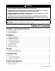
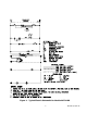
ModPac II™ Vertical Modular Wall-Mount Air Conditioners Installation and Operation Manual MODELS AVP 24-30-36-42-48-60 Supporting Member of 1. Description......................................... 5 2. Installation......................................... 8 3. Start-Up............................................19 4. Troubleshooting.................................20 5. Ratings & Specifications.....................24 6. Maintenance......................................27 7. Warranty.......................
How To Use This Manual This manual is intended to be a guide to Marvair's ModPac™ line of vertical air conditioners. It contains installation, troubleshooting, maintenance, warranty, and application information. The information contained in this manual is to be used by the installer as a guide only. This manual does not supersede or circumvent any applicable national or local codes.
WARNING • If the information in these instructions are not followed exactly, a fire may result causing property damage, personal injury or loss of life. • Read all instructions carefully prior to beginning the installation. Do not begin installation if you do not understand any of the instructions. • Improper installation, adjustment, alteration, service or maintenance can cause property damage, personal injury or loss of life.
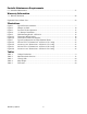
Periodic Maintenance Requirements 6.1 Scheduled Maintenance................................................................................................................ 27 Warranty Information 7.1 Warranty Statement.......................................................................................................................28 Exploded Views & Parts Lists..............................................................................................................29 Illustrations Figure 1.
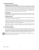
ModPac II™ A/C Description & Specs 1.1 General Description The Marvair ModPac II™ air conditioner line is a series of vertical wall-mounted air conditioning systems that provide heating and cooling for modular construction offices and classrooms. The series includes three cabinet sizes and nominal cooling capacities from 24,000 to 56,000 BTUH. Resistance heating elements are available in various wattages. The ModPac II™ models are designed for easy installation and service.
1.2 General Operation Refrigerant Cycle (Cooling Mode) The ModPac II™ A/C uses R-22 refrigerant in a conventional vapor-compression refrigeration cycle to transfer heat from air in an enclosed space to the outside. A double blower assembly blows indoor air across the evaporator. Liquid refrigerant passing through the evaporator is boiled into gas by heat removed from the air. The warmed refrigerant gas enters the compressor where its temperature and pressure are increased.
Figure 1.
Installation WARNING Failure to observe and follow Warnings and Cautions and these Instructions could result in death, bodily injury or property damage. Read this manual and follow its instructions and adhere to all Cautions and Warnings in the manual and on the Marvair unit. 2.1 Equipment Inspection Concealed Damage Inspect all cartons and packages upon receipt for damage in transit. Remove cartons and check for concealed damage. Important: keep the unit upright at all times.
C) The unit exhausts air. Be sure that the airflow is not impeded by shrubbery or other obstructions. 4. Airflow Requirements. Note the minimum CFM requirements (section 2.4). Keep duct lengths as short as possible. Do not obstruct airflow through the unit. Applications using duct work should be designed and installed in accordance with all applicable safety codes and standards.
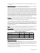
Motorized Damper - 0 to 450 cfm of Outside Air and Pressure Relief (Configuration B) The settings of the damper require a balometer and a thermometer for measuring internal and external temperatures. a. Measure the total supply air with a balometer. If the supply air is controlled by a manual fan speed controller, make certain that the air flow is in accordance with Table 3, Air Flow (CFM) at Various Static Pressures. This CFM is referred to as "C" in the illustration and equation below. b.
2.3 Installation Materials Installation Kits All ModPac II™ A/C units have built-in side flanges that function as side brackets. All models require and are shipped with a bottom mounting bracket. There is also an air intake hood factory installed behind the lower front panel. Standard Kit Components - Models AVP24-60: 1. One 12 Ga. "L"-shaped bottom bracket Accessories: The package may include other factory-supplied items (optional) as follows: Part # Description 50121 Digital thermostat.
Appropriate electrical supplies such as conduit, electrical boxes, fittings, wire connectors, etc. • High voltage wire, sized to handle the MCA (minimum circuit ampacity) listed on the data plate. • Over-Current Protection Device sized in accordance with the MFS (maximum fuse size) listed on the unit data plate. Duct materials usually are also needed in addition to the mounting hardware. To save time, design the duct work before mounting the unit.
system must be engineered to insure sufficient air flow through the unit to prevent over-heating of the heater element. This includes proper supply duct sizing, sufficient quantity of supply registers, adequate return and filter area. Duct work must be of correct material and must be properly insulated. Duct must be constructed of galvanized steel with a minimum thickness of .019" for the first three feet. Duct work must be firmly attached, secured and sealed to prevent air leakage.
2.6 "V" Damper Installation ® Figure 4. "V" Damper Installation 2.7 Bracket Installation 1. The ModPac II™ air conditioners have built-in mounting flanges. See Figure 5. 2. Refer to Figure 5. Attach the bottom support bracket to the wall using appropriate 3/8" diameter hardware. For example, on wooden structures, use 3/8 x 2-1/2 inch all-thread lag screws. The screws must penetrate the center of the wall stud. Drill a pilot hole in the stud to prevent it from splitting.
For units with electric heat, a one inch clearance is required around the duct extensions. The duct extensions must be constructed of galvanized steel with a minimum thickness of .019” as per the NFPA standards 90A & 90B. Figure 5. Wall Mounting Detail - Models AVP24-60 2.8 Mounting the Unit 1. For wiring into the back of unit, locate the lower of the two knock-outs on the wall side of the ModPac II™ A/C. Drill a one inch hole in the shelter wall to match this opening.
6. Apply a bead of silicone where the flashing and side brackets contact the unit and the building wall. 7. Fasten the flashing to the unit casing and the building wall using #10 x 1/2 inch sheet metal screws. 8. On the inside of the building, install the wall sleeves in the supply and return air openings. The sleeves may be trimmed to fit flush with the inside wall. For units with electric heat, a one inch clearance is required around the duct extensions.
after several minutes of operation the compressor's internal protector will trip. The compressor will then cycle on the protector until the phasing is corrected. Reverse operation for longer than one hour may have a negative impact on the bearings. Failure to ensure proper rotation will void the warranty of the compressor. High Voltage Wiring The power supply should have the proper voltage, phase, and ampacity for the selected model. 1.
5 FIVE (5) Figure 6a. Thermostat Wiring Detail MARVAIR®/SIMPLE COMFORT THERMOSTAT CONNECTION DIAGRAM FOR MARVAIR MODPAC II™ AIR CONDITIONERS THERMOSTAT PART NUMBER 50121/ SC2010-SL R G Y W C O B 50124/ SC3001-SL Rc RH G Y W C O B 50123/ SC5011-SL Rc RH G Y W C O B 50107/ SC5811-SL R G Y1 W1 C Y2 W2 MODPAC II R G Y W C LOW VOLTAGE TERMINAL BOARD O/B Figure 6b.
Start-Up Important: If your unit has a crankcase heater be sure that the crankcase heater has been energized for at least 24 hours prior to start-up of the unit. Double check all electrical connections before applying power. Various thermostats can be used to control the air conditioner. The thermostat may have a fan switch with an Automatic and On positions, a system switch with Heat, Cool, and Off positions. The spec sheets have detailed description of the various Marvair® thermostats.
Troubleshooting 4.1 Overview A comprehensive understanding of the operation of the ModPac II™ air conditioner is a prerequisite to troubleshooting. Please read the Chapter 1 for basic information about the unit. Marvair® ModPac II™ air conditioners are thoroughly tested before they are shipped from the factory. Of course, it is possible that a defect may escape undetected, or damage may have occurred during transportation. However, the great majority of problems result from installation errors.
4.2 Failure Symptoms Guide PROBLEM/SYMPTOM A. Unit does not run. LIKELY CAUSE(S) CORRECTION 1. Power supply problem. 1. Check power supply for adequate phase and voltage. Check wiring to unit and external breakers or fuses. 2. Blown fuse or breaker. 2. Check circuit protection devices for continuity. 3. Shut off by external thermostat or thermostat is defective. 3. Check operation of wall-mounted thermostat. 4. Internal component or connection failure. 4. Check for loose wiring.
4.3 Compressor Troubleshooting NOTE: It is important to rule out other component failures before condemning the compressor. The following electrical tests will aid diagnosis: 1. Start-Up Voltage: Measure the voltage at the compressor terminals during start-up. The voltage must exceed the minimum shown in Table 4, section 2.2, or compressor failure is likely. A low voltage condition must be corrected. 2. Running Amperage: Connect a clamp-on type ammeter to the (common) lead to the compressor.
4.4 Electric Heat Controls Figure 7. Typical Configuration for Single Element Heater The electric heater assembly can have up to three individual heating elements. Each individual heating element is protected against overheating by its own dual function thermal cut-out switch. Additionally, a separate single function thermal cut-out switch protects the entire heater assembly.
Ratings and Specifications 5.1 Ratings & Specifications Table 1. CFM @ ESP (Wet Coil) MODEL 24 0.10 0.20 0.30 0.40 0.50 860 810 670 --- --- 30 1100 1000 920 810 --- 36 1310 1220 1150 1060 --- 42 --- 1650 1520 1450 1360 48 --- 1900 1760 1700 1620 60 --1900 1760 CFM = Cubic Feet per Minute - Indoor Air Flow ESP = External Static Pressure in Inches WG 1700 1620 Table 2. Ship Weight (Lbs.
5.2 Dimensional Data DIMENSIONS AVPA 24-36 N DAMPER AVPA 24 AVPA 30-36 Figure 8a. AVP24-36 ModPac II™ A/C - "N" Configuration (In Inches) Figure 8b.
AVPA 24 AVPA 30-36 Figure 8c. AVP24-36 ModPac II™ A/C - "B" Configuration (In Inches) Figure 8d.
Maintenance 6.1 Scheduled Maintenance Marvair® strongly recommends that the air conditioner be serviced a minimum of twice a year – once prior to the heating season and once prior to the cooling season. At this time the filters, evaporator coil, condenser coil, the cabinet, and condensate drains should be serviced as described below. Also at this time, the air conditioner should be operated in the cooling and heating cycles as described in Chapter 3, Start-Up.
Warranty 7.1 Limited Product Warranty If any part of your Marvair® Air Conditioner, Heat Pump or Unit Ventilator fails because of a manufacturing defect within fifteen months from the date of original shipment from Marvair or within twelve months from the date of original start-up, whichever is the earlier date, Marvair will furnish without charge, EXW Cordele, Georgia, the required replacement part.
EXPLODED VIEWS AND PARTS LISTS Current parts lists and exploded views of the unit can be found on our web site at www.marvair.com. Click on the Service and Parts in the menu on the left hand side of the Home page. From the drop down menu, select Exploded Views. Once here, you can select your air conditioner or heat pump. The units are grouped by model and by the refrigerant – R-22 or R-410A.