
Specifications


6
ModPac II, 9/09-15
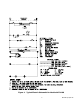
1.3 Electrical Diagrams
The compressor incorporates an internal PTC crankcase heater that functions as long as primary
power is available. The heater drives liquid refrigerant from the crankcase and prevents loss of
lubrication caused by oil dilution. Power must be applied to the unit for 24 hours before starting
the compressor. The compressor is energized with a contactor controlled by a 24 VAC pilot signal
(see Figure 1). The evaporator blower motor is cycled by the blower time delay relay.
NOTE: The ModPac II™ A/C models incorporate a 90 second purge cycle that runs the evapora-
tor blower after the thermostat is satised.
IMPORTANT
1.2 General Operation
Refrigerant Cycle (Cooling Mode)
The ModPac II™ A/C uses R-22 refrigerant in a conventional vapor-compression refrigeration
cycle to transfer heat from air in an enclosed space to the outside. A double blower assembly
blows indoor air across the evaporator. Liquid refrigerant passing through the evaporator is boiled
into gas by heat removed from the air. The warmed refrigerant gas enters the compressor where
its temperature and pressure are increased. The hot refrigerant gas condenses to liquid as heat is
transferred to outdoor air blown across the condenser by the condenser fan. Liquid refrigerant is
metered into the evaporator through capillary tubes to repeat the cycle.
Heating Mode
A wall-mounted thermostat controls the heating cycle of models which incorporate resistance
heating elements. On a call for heat, the thermostat closes the heat relay to energize the indoor
fan and the resistance elements.
Ventilation Options
• Manual damper capable of up to 15% of rated airow of outside air; eld adjustable, no pressure
relief. (Standard - Ventilation Conguration N)
• Motorized, two position damper (open and closed) capable of 0 to 450 cfm (maximum of 40%
of rated airow) of outside air; includes pressure relief. A 24-volt actuated motor controls the
damper from an external input such as: a time clock, CO2 sensor, energy management system
or manual switch. (Optional - Ventilation Conguration B)
• Manual damper capable of 15 to 450 cfm of outside air (up to a maximum of 40% of rated air
ow). No pressure relief. An external, eld installed front panel replaces standard front panel.
(Optional - “V” Damper )