Installation Operation and Maintenance Instructions Refrigerator Models 3CARM 6CARM 6CADM 8CARM
CONTENTS Unpacking your refrigerator................................................... Removing the packaging..................................................... Warranty Registration.......................................................... Installing your refrigerator..................................................... Selecting the location......................................................... Cabinet Clearances.............................................................. Leveling legs............
UNPACKING YOUR REFRIGERATOR Remove Packaging Warranty Registration Your refrigerator has been packed for shipment with all parts that could be damaged by movement securely fastened. Cut the banding material at the bottom of the carton, unfold the carton at the bottom and remove the carton from the appliance. Remove the plastic bag, styrofoam corner posts and any tape holding the door closed and internal components in place.
INSTALLING YOUR REFRIGERATOR Select Location Leveling Legs Cabinet Clearance To adjust the leveling legs, place the refrigerator on a solid surface and protect the floor beneath the legs to avoid scratching the floor. With the assistance of another person, lean the refrigerator back enough to access the front leveling legs and remove the weight. Raise or lower the legs to the required dimension by turning the legs.
GROUNDING METHOD AND ELECTRICAL REQUIREMENTS • • Do not splash or spray water from a hose on the refrigerator! Doing so may cause an electrical shock, which may result in severe injury or death. This unit should not, under any circumstances, be installed to an un-grounded electrical supply. Grounding Method This product is factory equipped with a power supply cord that has a three-pronged, grounded plug.
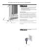
HANDLE INSTALLATION AND DOOR ALIGNMENT Handle Installation (Solid Door Models) 1. 2. Door Alignment Procedure Remove the handle, (2) screws, and 5/32” allen wrench from the bag shipped inside the cabinet. Locate handle opposite the hinges and secure in place using the (2) screws and the allen wrench. (See Figure 5). The door should be parallel to the sides and top of the refrigerator.
USING YOUR MICROSENTRY™ REFRIGERATOR CONTROL Alarm C Door Switch Control Set NOTE Colder Press and Hold Warmer ON/OFF Press and Hold Figure 7 During initial startup, or anytime power is interrupted, there will be an approximate 5 minute delay before the refrigerator starts. During this period the controller will be assessing the temperature in the refrigerator and the display will appear erratic, this is normal. The desired set temperature can be programmed during this start up period.
USING YOUR MICROSENTRY™ REFRIGERATOR CONTROL See the “care and cleaning” section for cleaning instructions. Alarm Mute Press any key to mute the audible portion of an alarm. NOTE-This action will only mute the alarm. If the condition that caused the alarm continues, the alarm code will continue to flash and will sound for 20 seconds every 60 minutes. Turning Refrigerator Off To turn refrigerator off, press and hold “ON/OFF” button for three (3) seconds. “OFF” will appear on the display.
DIMENSIONS FOR MODEL 3CARM SOLID DOOR 37-1/16” (94.13 cm) 15-7/8” (40.34 cm) 24-19/32” (62.34 cm) 14-7/8” (37.78 cm) 23-9/32” (59.13 cm) 33-3/4” to 34-3/4” (85.7 to 88.3 cm) 3” to 4” 7.62 to 10.2cm) 21-3/16” (53.82 cm) RECOMMENDED ROUGH IN OPENING DIMENSIONS, MODEL 3CARM SOLID DOOR Electrical Requirements: A 115 volt, 15 amp dedicated circuit is required. A 3 prong grounded receptacle is required. Power outlet can be located in the back wall behind unit.
DIMENSIONS FOR MODEL 3CARM WITH GLASS DOOR 36-15/16” (93.83 cm) 16-19.32” (42.14 cm) 25-7/32” (64.06 cm) 14-7/8” (37.78 cm) 23-9/32” (59.13 cm) 33-3/4” to 34-3/4” (85.7 to 88.3 cm) 3” to 4” 7.62 to 10.2cm) 21-3/16” (53.82 cm) RECOMMENDED ROUGH IN OPENING DIMENSIONS, MODEL 3CARM GLASS DOOR Electrical Requirements: A 115 volt, 15 amp dedicated circuit is required. A 3 prong grounded receptacle is required. Power outlet can be located in the back wall behind unit.
DIMENSIONS FOR MODEL 6CARM SOLID DOOR 47-3/32” (119.61 cm) 24-7/8” (63.20 cm) 25-11/32” (64.36 cm) 24-3/32” (61.19 cm) 23-7/8” (60.66 cm) 33-3/4” to 34-3/4” (85.7 to 88.3 cm) 3” to 4” 7.62 to 10.2cm) 22” (55.88 cm) RECOMMENDED ROUGH IN OPENING DIMENSIONS, MODEL 6CARM SOLID DOOR Electrical Requirements: A 115 volt, 15 amp dedicated circuit is required. A 3 prong grounded receptacle is required. Power outlet can be located in the back wall behind unit.
DIMENSIONS FOR MODEL 6CARM GLASS DOOR 46-7/8” (119.08 cm) 25-19/32” (65.0 cm) 26-1/32” (66.12 cm) 24-3/32” (61.19 cm) 23-7/8” (60.66 cm) 33-3/4” to 34-3/4” (85.7 to 88.3 cm) 3” to 4” 7.62 to 10.2cm) 22” (55.88 cm) RECOMMENDED ROUGH IN OPENING DIMENSIONS, MODEL 6CARM GLASS DOOR Electrical Requirements: A 115 volt, 15 amp dedicated circuit is required. A 3 prong grounded receptacle is required. Power outlet can be located in the back wall behind unit.
DIMENSIONS FOR MODEL 6CADM 46-7/8” (119.08 cm) 25-19/32” (65.0 cm) 26-1/32” (66.12 cm) 23-7/8” (60.66 cm) 24-3/32” (61.19 cm) 31-1/8” to 32-1/8” (79.05 to 81.60 cm) 3” to 4” 7.62 to 10.2cm) 22” (55.88 cm) RECOMMENDED ROUGH IN OPENING DIMENSIONS, MODEL 6CADM Electrical Requirements: A 115 volt, 15 amp dedicated circuit is required. A 3 prong grounded receptacle is required. Power outlet can be located in the back wall behind unit.
DIMENSIONS FOR MODEL 8CARM 52-15/16” (134.47 cm) 30-7/8” (78.44 cm) 25-11/32” (64.36 cm) 24-3/32” (61.19 cm) 29-7/8” (75.90 cm) 33-3/4” to 34-3/4” (85.7 to 88.3 cm) 3” to 4” 7.62 to 10.2cm) 22” (55.88 cm) RECOMMENDED ROUGH IN OPENING DIMENSIONS, MODEL 8CARM Electrical Requirements: A 115 volt, 15 amp dedicated circuit is required. A 3 prong grounded receptacle is required. Power outlet can be located in the back wall behind unit.
FEATURES 3CARM Features Probe Port (optional) There are three full depth adjustable shelves for flexibility of content storage. The shelves can move up or down to accommodate various content sizes. To adjust the shelves, simply lift up and pull forward. The optional probe port is a hole from the inside to the outside of the unit, which could be located on the top, side, or back of the unit. After inserting your wires or probe, seal the hole tightly with caulk, putty, foam, etc. for proper operation.
ENERGY SAVING TIPS AND CARE AND CLEANING Condenser The following suggestions will minimize the cost of operating your refrigeration appliance. 1. Do not install your appliance next to a hot appliance, (ovens, glassware washers, etc.). heating air duct, or other heat sources. 2. Install product out of direct sunlight. 3. Ensure the toe grille vents at front of unit beneath door are not obstructed and kept clean to allow ventilation for the refrigeration system to expel heat. 4.
TROUBLESHOOTING YOUR REFRIGERATOR • Before You Call for Service If the unit appears to be malfunctioning, read through this manual first. If the problem persists, check the troubleshooting guide below. Locate the problem in the guide and refer to the cause and its remedy before calling for service. The problem may be something very simple that can be solved without a service call. However, it may be required to contact your dealer or a qualified service technician.
COMMERCIAL PRODUCT WARRANTY Entire Product - One Year Parts and Labor Warranty AGA MARVEL warrants to the original purchaser that it will supply all necessary parts and labor to repair or replace in the end user’s establishment, any component which is found by an authorized representative of AGA MARVEL to be defective in materials or workmanship, subject to the conditions and exclusions stated below, for a period of one year from the date of purchase by the end user.
APPENDIX A, ADDITIONAL MICROSENTRY™ FEATURES Information Menu / Lockout Key To access the information menu, press the SET key, and immediately release it. In the information menu, a 2 or 3 digit code will be displayed representing each entry in the information menu. The first code displayed will be t1. With each sequential press and release of the SET key, the following codes will appear in this order: t1, thi, tLo, Ahi, ALo, AdL, cnd, and Loc.
www.agamarvel.com 1260 E. VanDeinse St. Greenville MI 48838 800.223.3900 41011808-EN Rev G 10/28/11 All specifications and product designs subject to change without notice. Such revisions do not entitle the buyer to corresponding changes, improvements, additions, replacements or compensation for previously purchased products.