Installation Operation and Maintenance Instructions Keg Dispenser 61HK (Marvel) 6OHK (Outdoor)
CONTENTS Unpacking your refrigerator........................................... Removing interior packaging...................................... Warranty Registration.................................................. Installing your refrigerator.............................................. Selecting the location................................................. Cabinet Clearances.................................................... Outdoor installation....................................................
UNPACKING YOUR REFRIGERATOR Warranty Registration It is important you send in your warranty registration card immediately after taking delivery of your refrigerator. EXCESSIVE WEIGHT HAZARD The following information will be required when registering your unit. Service Number Serial Number Date of Purchase Dealer’s name and address Use two or more people to move product. Failure to do so can result in back or other injury.
INSTALLING YOUR REFRIGERATOR Leveling Legs Select Location Adjustable legs at the front and rear corners of the unit should be set so the unit is firmly positioned on the floor and level from side to side and front to back. The overall height of your Marvel refrigerator may be adjusted from 333⁄4" (85.7cm) with the leveling legs turned in, and up to 343⁄4" (88.3cm) with the leveling legs extended. The proper location will ensure peak performance of your appliance.
ELECTRICAL CONNECTION AND USING YOUR REFRIGERATOR Setting the temperature control: • • • • • Initially set the cold control midway between the numbers three (3) and four (4). After at least 2 hours adjust to the temperature that suits you. The higher the number you select, the cooler the temperature. (See figure 5). The temperature range of the refrigerator is from 33° to 52°F (1° to 11°C). Electrical Shock Hazard Do not use an extension cord with this appliance.
USING YOUR REFRIGERATOR Shelving If you are using a quarter barrel of beer, you can add shelf space for keeping your mugs chilled. The quarter barrel must set on the floor, it cannot fit on the shelf, see Figure 8. Be sure the white floor plate is in the bottom of the interior compartment before positioning the barrel. The unit is shipped with the (2) shelves taped in place in the lower shelf position. Remove them from the refrigerator and arrange them as follows when setting up your unit.
USING YOUR REFRIGERATOR This beer dispensing unit will support one half (1⁄2) barrel or one quarter (1⁄4) barrel. The double draft tower units can support two sixth (1⁄6) barrels of beer. See chart below for quantity of beer in each barrel size. Tools required for installation: Phillips screwdriver Pliers Adjustable wrench or a 11⁄8" open end wrench Barrel Sizes 1/6 barrel 1/4 Barrel 1/2 Barrel Height 5 23 ⁄16" (59.2 cm) 13 14 ⁄16" (37.6 cm) 235⁄16" (59.2 cm) Diameter 9 ⁄4" (23.5 cm) 17" (43.
USING YOUR REFRIGERATOR Double Dispense Tower Kit Connect A to A ,etc........ Single Dispense Tower Kit Connect A to A ,etc........
USING YOUR REFRIGERATOR Chain-The chain is fastened and taped to the top of the interior liner. Untape it and secure CO2 tank in place in the back right corner. Figure 20 5. 6. 7. 8. 9. Handle in up position the 11⁄2" hole in the counter top and the hole in the top of the keg refrigerator. Mount the tower to the counter top with the 4 screws provided. Mount the regulator to the CO2 tank (connection B ) use the new plastic washer you received from the gas supply company.
USING YOUR REFRIGERATOR CO2 Regulator Your beer dispenser comes equipped with a 5 pound CO2 tank and a dual gauge regulator. The lower gauge should be reading approximately 750 psi (52 bar) when the tank is properly filled and the tank is not in the refrigerator (at room temperature). The tank will read less when chilled. Use this lower gauge as an indicator of how much CO2 you have left in the tank. The upper gauge reads the pressure being supplied to the beer keg.
DRAIN KIT INSTALLATION (OPTIONAL) Drip Tray Hole in Cabinet Washer Nut Drain Hose Bottle Cap Bottle Figure 25 Drain Kit Installation: (See Figure 25) 1. Remove the cardboard box with the drip tray from inside the cabinet and remove the parts from the box. 2. Remove the nut and washer from the drip tray. 3. Push the threaded stem of the drip tray through the hole in the top of the cabinet and secure from inside the cabinet with the washer and the hex nut. Do not overtighten the nut. 4.
CARE AND CLEANING Cleaning and Maintaining Dispensing System The dispensing system needs to be cleaned between usage to prevent spoilage and/or foul taste in your beer. Tap Cleaning Kit This is an optional item (part number 42242373) Kit includes everything to quickly clean tap. Includes cleaning solution, pump, mixing bottle, brush and wrench. Faucet Cleaning Turn off the gas supply with the shutoff valve under the regulator (see Figure 22) and open the faucet to relieve the pressure.
CARE AND CLEANING AND ENERGY SAVING TIPS Cabinet The painted cabinet can be washed with either a mild soap and water and thoroughly rinsed with clear water. NEVER use abrasive scouring cleaners. Interior Wash interior compartment with mild soap and water. Do NOT use an abrasive cleaner, solvent, polish cleaner or undiluted detergent. Care of Unit 1. Avoid leaning on the door, you may bend the door hinges or tip the unit. 2.
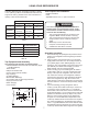
DIMENSIONS FOR MODELS 61HK SOLID DOOR 47" (119.4cm) 2511⁄16" (65.2cm) 1115⁄16" (30.3cm) 11" (27.9cm) 121⁄4" (31.1cm) 333⁄4" to 343⁄4" (85.7 to 88.3cm) 237⁄8" (60.7cm) 22" (55.9cm) 3" to 4" (7.6 to 10.2cm) 241⁄16" (61.1cm) 26" (66.0cm) RECOMMENDED ROUGH IN OPENING DIMENSIONS, 61HK SOLID DOOR Electrical Requirements: A grounded 115 volt, 15 amp dedicated circuit is required. A GFCI receptacle may be required for outdoor units. Power outlet can be located in the back wall behind unit.
DIMENSIONS FOR MODELS 6OHK-SS SOLID DOOR 47" (119.4cm) 267⁄16" (67.2cm) 1115⁄16" (30.3cm) 11" (27.9cm) 121⁄4" (31.1cm) 333⁄4" to 343⁄4" (85.7 to 88.3cm) 237⁄8" (60.7cm) 22" (55.9cm) 3" to 4" (7.6 to 10.2cm) 245⁄16" (61.8cm) 263⁄4" (68.0cm) RECOMMENDED ROUGH IN OPENING DIMENSIONS, 6OHK-SS SOLID DOOR Electrical Requirements: A grounded 115 volt, 15 amp dedicated circuit is required. A GFCI receptacle may be required for outdoor units. Power outlet can be located in the back wall behind unit.
DIMENSIONS FOR MODEL 61HK SOLID OVERLAY DOOR 4627⁄32" (119.0cm) 1115⁄16" (30.3cm) 121⁄4" (31.1cm) 11" (27.9cm) 333⁄4" to 343⁄4" (85.7 to 88.3cm) 3" to 4" (7.6 to 10.2cm) 22" (55.9cm) 235⁄16" (59.2cm) RECOMMENDED ROUGH IN OPENING DIMENSIONS, 61HK SOLID OVERLAY DOOR Electrical Requirements: A grounded 115 volt, 15 amp dedicated circuit is required. Power outlet can be located in the back wall behind unit. Add 1" to depth for thickness of plug, or recess outlet 1" into the wall.
DIMENSIONS FOR MODEL 6OHK-SSX SOLID DOOR 22" (55.9cm) 267⁄16" (67.2cm) 1115⁄16" (30.3cm) 47" (119.4cm) 11" (27.9cm) 121⁄4" (31.1cm) 3615⁄16" (93.8cm) 63⁄8" (16.2cm) 245⁄16" (61.8cm) 237⁄8" (60.7cm) 263⁄4" (68.0cm) Electrical Requirements: A grounded 115 volt, 15 amp dedicated circuit is required. A GFCI receptacle may be required for outdoor units. Power outlet can be located in the back wall behind unit. Follow all local building codes when installing electrical and unit.
FULL OVERLAY PANEL INSTALLATION INSTRUCTIONS Step 3: Remove gasket Step 1: Verify door alignment Verify that the door is aligned correctly with the cabinet prior to fabricating the custom panel. Failure to do so may result in mis-alignment of the custom panel with the hinge bracket. The door should be parallel to the sides and top of the refrigerator.
FULL OVERLAY PANEL INSTALLATION INSTRUCTIONS This is also a convenient time to locate and drill the holes for your handle. Most often the handle is to match that of the surrounding cabinetry. If your handle attaches from the back-side of the custom panel, locate the mounting holes while the panel is attached to the door and cabinet. After the panel is removed from the door, drill the mounting holes from the front, to the recommended diameter of the handle manufacturer.
FULL OVERLAY PANEL INSTALLATION INSTRUCTIONS BRASS EXTENSION SPRING WASHER Clearance hole through door gasket channel CAM NUT LOCK #10 Wood Screw PHILLIPS SCREW 15/32 HOLE 13/16 COUNTER BORE 7/16 DEEP Back of door INNER DOOR 3/4 INCH WOOD PANEL Figure 34 SECTION A-A SCALE 1 : 1 Figure 33 Step 8: Assemble the lock parts Two (2) lock extensions are supplied with the lock. Use the longer extension for a 3⁄4" thick overlay panel and the shorter one for a 5⁄8" thick panel.
TROUBLESHOOTING YOUR REFRIGERATOR AND OBTAINING SERVICE Before You Call for Service If the unit appears to be malfunctioning, read through this manual first. If the problem persists, check the troubleshooting guide below. Locate the problem in the guide and refer to the cause and its remedy before calling for service. The problem may be something very simple that can be solved without a service call. However, it may be required to contact your dealer or a qualified service technician.
OBTAINING SERVICE If Service is Required: • • • • • If the product is within the first year warranty period please call AGA MARVEL Customer Service at 800.223.3900 for directions on how to obtain warranty coverage in your area. If the product is outside the first year warranty period, AGA MARVEL Customer Service can provide recommendations of service centers in your area. A listing of authorized service centers is also available at www. agamarvel.com under the service and support section.
HOUSEHOLD PRODUCT WARRANTY Entire Product Limited One Year Parts and Labor Warranty Parts or Service Not Supplied or Designated by AGA MARVEL AGA MARVEL warrants that it will supply all necessary parts and labor to repair or replace in the end user’s home or office, any component which proves to be defective in material or workmanship, subject to the condition and exclusions stated below, for a period of one year from the date of purchase by the end user.
www.agamarvel.com 1260 E. VanDeinse St. Greenville MI 48838 800.223.3900 41012918-EN Rev B 12/3/12 All specifications and product designs subject to change without notice. Such revisions do not entitle the buyer to corresponding changes, improvements, additions, replacements or compensation for previously purchased products.
Instructions d’installation, d’utilisation et d’entretien Réfrigérateur distributeur de bière en fût 61HK (Marvel) 6OHK (Extérieur)
CONTENU Déballage de votre réfrigérateur distributeur................ Enlèvement de l’emballage........................................ Enregistrement de la garantie..................................... Installation de votre réfrigérateur distributeur................ Choix de l’emplacement............................................ Écartements par rapport à l’armoire.......................... Installation à l’extérieur ............................................. Pieds de mise à niveau....................
DÉBALLAGE DE VOTRE RÉFRIGÉRATEUR DISTRIBUTEUR Enregistrement de la garantie Il est important que vous postiez votre carte de garantie immédiatement après avoir pris livraison de votre réfrigérateur. AVERTISSEMENT RISQUE DE POIDS EXCESSIF Les informations suivantes seront nécessaires au moment de l’enregistrement de votre appareil : Référence de service Numéro de série Date d’achat Nom et adresse du revendeur Utilisez deux personnes ou plus pour bouger et empiler le produit.
INSTALLATION DE VOTRE RÉFRIGÉRATEUR DISTRIBUTEUR Choix de l’emplacement Pieds de mise à niveau Un bon emplacement assurera une performance de pointe pour votre appareil. Nous recommandons un endroit où l’appareil ne sera pas exposé directement au rayonnement solaire et restera écartée de sources de chauffage.
RACCORDEMENT ÉLECTRIQUE ET UTILISATION DE VOTRE RÉFRIGÉRATEUR REMARQUE NOTE AVERTISSEMENT Un disjoncteur sur détection de courant de fuite (GFCI) provoque des déclenchements intempestifs qui arrêtent l’appareil. Ce type de protection n’est en général pas utilisé sur de l’équipement électrique qui doit tourner sans surveillance pendant de longues périodes, sauf si c’est imposé par les normes de construction et réglementations locales.
UTILISATION DE VOTRE RÉFRIGÉRATEUR Rangement Si vous utilisez un quart de baril de bière (fût de 29,33 L), vous pouvez ajouter un espace sur étagère pour garder vos chopes réfrigérée. Le fût d’un quart de baril doit reposer sur le fond, il ne peut pas tenir sur l’étagère (Voir la Figure 8). Assurez-vous que la plaque blanche du fond soit au fond du compartiment intérieur avant de positionner le tonneau. Le réfrigérateur est livré avec deux (2) étagères fixées par bande en position la plus basse.
UTILISATION DE VOTRE RÉFRIGÉRATEUR Le distributeur de bière supporte un baril d’un demi (1⁄2) ou d’un quart (1⁄4). Les distributeurs doubles de bière pression peuvent supporter deux barils de bière d’un sixième (1/6). Consultez le tableau ci-dessous pour la quantité de bière de chaque taille de baril. Outils nécessaires pour l’installation : Tournevis à pointe Phillips Pinces Clé à molette ou clé à fourche de 11⁄8" Tailles de baril Baril 1/6 Baril 1/4 Baril 1/2 Hauteur 5 23 ⁄16" (59.
UTILISATION DE VOTRE RÉFRIGÉRATEUR Kit de tour à distribution unique Relier A à A ,etc...... Kit de tour à distribution double Relier A à A ,etc......
UTILISATION DE VOTRE RÉFRIGÉRATEUR Chaîne – La chaîne est fixée par de la bande adhésive sur le haut du revêtement intérieur. Dégagez-la et arrimez la bouteille de CO2 en place dans l’angle droit du fond. 9. Accrochez le coupleur sur le fût. Vérifiez que la poignée blanche est en position levée comme c’est montré. Alignez les pointes de col sur le goulot de fût avec l’ouverture dans le coupleur. Tournez le coupleur en sens horaire ↻ jusqu’à son arrêt.
UTILISATION DE VOTRE RÉFRIGÉRATEUR Régulateur de CO2 Votre distributeur de bière est livré équipé avec une bouteille de CO2 de 5 livres et un régulateur à deux manomètres. Le manomètre inférieur doit indiquer environ 750 psi (52 bar) quand la bouteille est correctement remplie et avant d’être mise dans le réfrigérateur (à température ambiante). L’indication sera plus faible avec la bouteille réfrigérée. Utilisez ce manomètre inférieur comme indicateur de la quantité de gaz qui reste dans la bouteille.
INSTALLATION D’UN KIT DE DRAINAGE (OPTIONNEL) Plateau d’égouttage Trou dans l’enceinte Rondelle Écrou Tuyau de drainage Capsule de bouteille Bouteille Figure 25 Installation du kit de drainage : (Voyez la Figure 25). 1. Sortez la boîte en carton contenant le plateau d’égouttage de l’intérieur de l’appareil et sortez les pièces de cette boîte. 2. Ôtez l’écrou et la rondelle du bac d’égouttage. 3.
ENTRETIEN ET NETTOYAGE Nettoyage et entretien du système de distribution Le système de distribution a besoin d’être nettoyé entre ses utilisations pour éviter du gaspillage et/ou un mauvais goût pour la bière. Kit de nettoyage de robinetterie C’est un article optionnel (N° de pièce 42242373), ce kit inclut tout ce qu’il faut pour nettoyer rapidement la robinetterie. Solution de nettoyage, pompe, bouteille pour mélange, brosse et clé.
ENTRETIEN ET NETTOYAGE ET CONSEILS POUR LES ÉCONOMIES D’ÉNERGIE Armoire L’armoire peinte peut se laver avec une solution savonneuse douce, puis soigneusement se rincer à l’eau potable. N’utilisez JAMAIS de produits nettoyants abrasifs. Intérieur Lavez le compartiment intérieur avec une solution savonneuse douce. N’utilisez pas de nettoyant abrasif, de solvant, de produit nettoyant/polissant ou de détergent non-dilué. Entretien de l’appareil 1. 2. 3. 4.
DIMENSIONS POUR PORTE PLEINE DE 61HK 47" (119.4cm) 2511⁄16" (65.2cm) 1115⁄16" (30.3cm) 11" (27.9cm) 121⁄4" (31.1cm) 333⁄4" to 343⁄4" (85.7 to 88.3cm) 237⁄8" (60.7cm) 3" to 4" (7.6 to 10.2cm) 22" (55.9cm) 241⁄16" (61.1cm) 26" (66.0cm) DIMENSIONS BRUTES D’OUVERTURE RECOMMANDÉES POUR PORTE PLEINE DE 61HK ATTENTION Besoins électriques : Un circuit secteur dédié en 115 V supportant 15 A est nécessaire. Une prise avec protection GFCI peut être nécessaire avec les modèles pour extérieur.
DIMENSIONS POUR PORTE PLEINE DE 6OHK-SS 47" (119.4cm) 267⁄16" (67.2cm) 1115⁄16" (30.3cm) 11" (27.9cm) 121⁄4" (31.1cm) 333⁄4" to 343⁄4" (85.7 to 88.3cm) 237⁄8" (60.7cm) 3" to 4" (7.6 to 10.2cm) 22" (55.9cm) 245⁄16" (61.8cm) 263⁄4" (68.0cm) DIMENSIONS BRUTES D’OUVERTURE RECOMMANDÉES POUR PORTE PLEINE DE 6OHK-SS ATTENTION Besoins électriques : Un circuit secteur dédié en 115 V supportant 15 A est nécessaire. Une prise avec protection GFCI peut être nécessaire avec les modèles pour extérieur.
DIMENSIONS POUR PORTE À REVÊTEMENT PLEIN DE MODÈLE 61HK 4627⁄32" (119.0cm) 1115⁄16" (30.3cm) 121⁄4" (31.1cm) 11" (27.9cm) 333⁄4" to 343⁄4" (85.7 to 88.3cm) 3" to 4" (7.6 to 10.2cm) 22" (55.9cm) 235⁄16" (59.2cm) DIMENSIONS BRUTES D’OUVERTURE RECOMMANDÉES POUR PORTE À REVÊTEMENT DE 61HK ATTENTION Besoins électriques : Un circuit secteur dédié en 115 V supportant 15 A est nécessaire. Une prise avec protection GFCI peut être nécessaire avec les modèles pour extérieur.
DIMENSIONS POUR PORTE PLEINE DE 6OHK-SSX 22" (55.9cm) 267⁄16" (67.2cm) 1115⁄16" (30.3cm) 47" (119.4cm) 11" (27.9cm) 121⁄4" (31.1cm) 3615⁄16" (93.8cm) 63⁄8" (16.2cm) 245⁄16" (61.8cm) 237⁄8" (60.7cm) 263⁄4" (68.0cm) ATTENTION Besoins électriques : Un circuit secteur dédié en 115 V supportant 15 A est nécessaire. Une prise avec protection GFCI peut être nécessaire avec les modèles pour extérieur. La prise secteur peut être située sur la cloison murale derrière l’appareil.
INSTRUCTIONS D’INSTALLATION DE PANNEAU DE REVÊTEMENT COMPLET REMARQUE NOTE ATTENTION Étape 1 : Vérification de l’alignement de porte Vérifiez que la porte est correctement alignée par rapport à l’armoire avant de fabriquer le panneau sur mesures. Sinon cela peut amener un désalignement du panneau sur mesures avec le support de charnière. La porte doit être parallèle avec les côtés et le dessus de l’armoire.
INSTRUCTIONS D’INSTALLATION DE PANNEAU DE REVÊTEMENT COMPLET Étape 6 : Percez les trous de montage du panneau Maintenez à nouveau le panneau sur la porte comme à l’étape précédente et percez les avant-trous de vis, situés dans le logementl de joint, afin de fixer le panneau de revêtement à la porte. Choisissez la taille du trou à partir du Tableau D.
INSTRUCTIONS D’INSTALLATION DE PANNEAU DE REVÊTEMENT COMPLET EXTENSION EN LAITON BRASS EXTENSION RONDELLE ÉLASTIQUE SPRING WASHER Trou de passage à travers joint de porte de canal CAM CAME ÉCROU NUT VERROU LOCK vis à bois #10 VIS PHILLIPS PHILLIPS SCREW TROU DE 15⁄32” 15/32 HOLE CONTRE-ALÉSAGE DE 13 ⁄16” DE 13/16 COUNTER PROFONDEU BORE 7/16 DEEP 7⁄16” INTÉRIEUR DE INNER PORTE DOOR PANNEAU 3/4 INCHDE BOIS DE 3⁄4” WOOD PANEL Intérieur De Porte Figure 34 SECTION A-A SECTION A-A SCALE 1 :1:1 1 ÉCHELLE
DÉPANNAGE DE VOTRE RÉFRIGÉRATEUR Avant d’appeler pour du service Si l’appareil semble présenter un dysfonctionnement, commencez par bien relire son manuel. Si le problème persiste, consultez le guide de dépannage qui suit. Identifiez le problème dans ce guide et consultez les colonnes de causes et de remèdes avant d’appeler pour du service. Le problème peut être quelque chose de très simple qui peut se résoudre sans demander une intervention de service.
OBTENTION DE SERVICE Si du service est nécessaire : • • • • • Si le produit est encore dans sa première année de garantie, veuillez appeler le service à la clientèle d’AGA MARVEL au 800.223.3900 pour avoir des instructions sur la façon d’obtenir une couverture sous garantie dans votre secteur. Si le produit est sorti de sa première année de garantie, le service à la clientèle d’AGA MARVEL peut vous fournir des recommandations sur les centres de service de votre secteur.
GARANTIE DE L’APPAREIL À USAGE DOMESTIQUE Pièces ou service non fournis ou conçus par AGA MARVEL Appareil complet Garantie limitée d’un an sur pièces et maind’œuvre Les garanties qui précèdent ne s’appliquent pas non plus si : AGA MARVEL garantit qu’il fournira toutes les pièces et la maind’œuvre nécessaires pour réparer ou remplacer, au domicile ou au bureau de l’utilisateur final, tout composant avéré défectueux du fait des matériaux ou de la main-d’œuvre, en tenant compte des conditions et exclusions
www.agamarvel.com 1260 E. VanDeinse St. Greenville MI 48838 800.223.3900 41012918-FR Rev B 12/3/12 Toutes les spécifications et les conceptions des produits sont sujettes à des changements sans préavis. De telles révisions ne donnent aucun droit pour l’acheteur de produits antérieurs à bénéficier de ces changements, améliorations, ajouts, remplacements, ni de recevoir une compensation.