GE T TING STARTED QUICK REFERENCE GUIDE M ARVEL UNDERCOUNTER REFRIGERATION MLCR215-SS01A MLCR215-IS01A MOCR215-SS01A MACR214-BS01A MACR214-SS01A MACR215-SS01A T H E O R I G I N A L R E F R I G E R AT I O N E X P E R T S S I N C E 1 8 9 2
CONTENTS Contents: Important Safety Instructions Safety information ...............................................................2 Unpacking your appliance ................................................. 3 Installing your appliance ......................................................4 Electrical ..............................................................................5 Cutout dimensions ..............................................................7 Product dimensions ..........................
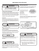
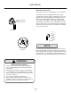
UNPACKING YOUR APPLIANCE ! Warranty Registration WARNING It is important you send in your warranty registration card immediately after taking delivery of your appliance or you can register online at www.marvelrefrigeration.com. EXCESSIVE WEIGHT HAZARD Use two or more people to move product. Failure to do so can result in personal injury. The following information will be required when registering your appliance.
INSTALLING YOUR APPLIANCE Select Location The proper location will ensure peak performance of your appliance. We recommend a location where the unit will be out of direct sunlight and away from heat sources. To ensure your product performs to specifications, the recommended installation location temperature range is from 50 to 100°F (10 to 38°C). Front grille screws Cabinet Clearance Ventilation is required from the bottom front of the appliance. Keep this area open and clear of any obstructions.
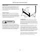
INSTALLING YOUR APPLIANCE General Installation Leveling Information 1. Use a level to confirm the unit is level. Level should be placed along top edge and side edge as shown. 1 Figure 3 2. If the unit is not level, adjust the legs on the corners of the unit as necessary. Figure 4 3. Confirm the unit is level after each adjustment and repeat the previous steps as needed.
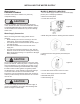
ELECTRICAL Electrical Connection A grounded 115 volt, 15 amp dedicated circuit is required. This product is factory equipped with a power supply cord that has a three-pronged, grounded plug. It must be plugged into a mating grounding type receptacle in accordance with the National Electrical Code and applicable local codes and ordinance. If the circuit does not have a grounding type receptacle, it is the responsibility and obligation of the customer to provide the proper power supply.
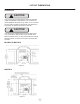
CUTOUT DIMENSIONS PREPARE SITE ! CAUTION Your product has been designed for either free-standing or built-in installation. When built-in, your unit does not require additional air space for top, sides, or rear. However, the front grille must NOT be obstructed, and clearance is required for an electrical connection in the rear. ! CAUTION Unit can NOT be installed behind a closed cabinet door.
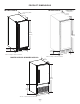
PRODUCT DIMENSIONS MLCR215-IS01A MLCR215-SS01A Not Including Handle 22 5/16” (567mm)* Includes 3/4”(20mm) Overlay Panel 22 5/16” (567mm)* 34 1/16” (865mm) 3 3/8” (85mm) 34 1/16” (865mm) 14 7/8” (378mm) 3 3/8” (85mm) *Add 3/4” to depth for water line clearance *Add 3/4” to depth for water line clearance MACR214-BS01A & MACR214-SS01A 17” (432mm) 24 3/4” (629mm) 8 15/16” (227mm) 13 15/16” (354mm) *Add 1/2” to depth for water line clearance 8 14 7/8” (378mm)
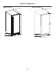
PRODUCT DIMENSIONS MOCR215-SS01A MACR215-SS01A Not Including Handle 22 5/16” (567mm)* Not Including Handle 22 5/16” (567mm)* 32” (813mm) 3” (76mm) 34 1/16” (865mm) 3 3/8” (85mm) 14 7/8” (378mm) *Add 3/4” to depth for water line clearance 14 7/8” (378mm) *Add 3/4” to depth for water line clearance 9
INSTALLING THE WATER SUPPLY Water Hookup PREPARE PLUMBING The water valve uses a standard 1/4” (6.35 mm) compression fitting. ! CAUTION MLCR215, MACR215 & MOCR215 1. Turn off water supply and disconnect electrical supply product prior to attempting installation. 2. Remove the back panel. 3. Locate water valve inlet. Plumbing installation must observe all state and local codes. All water and drain connections MUST BE made by a licensed/qualified plumbing contractor.
INSTALLING THE WATER SUPPLY MACR214 1. Turn off water supply and disconnect electrical supply product prior to attempting installation. 2. Remove the grille and access panel (if equipped) along with the back panel. 3. Locate water valve in the front of the unit and thread water supply line through. Figure 14 NOTE Route the water supply line through the unit so it does not come into contact with any internal components other than the solenoid valve. Normal operation creates some vibration.
DOOR ADJUSTMENTS Door Adjustments (MLCR215, MOCR215 & MACR215) Door Adjustments (MACR214) HINGE COVER CHECKING DOOR ALIGNMENT Hinge cover included with the literature bag is optional. To install hinge cover: The unit’s door is aligned at the factory before shipment. However, its alignment could have been disturbed during shipment. • Door Alignment and Adjustment Press hinge cover squarely over hinge. Hinge Cover To align and adjust the door 1. Loosen (do not remove) top and bottom hinge screws.
DOOR REVERSAL Reversing the Door MLCR215, MACR215 & MOCR215 Location of the unit may make it desirable to mount the door on the opposite side of the cabinet. The hinge hardware will be removed and reinstalled on the opposite side of the cabinet. TO REVERSE THE DOOR Figure 21 5. Remove door by tilting forward and lifting door off bottom hinge. Retain shoulder washers; they will be reused. 6. Remove three screws from hinge holes on the opposite side. Reinstall into holes where the hinge was removed.
DOOR REVERSAL Install top hinge and door: Reversing the Door 1. Install the top hinge. Do not tighten. MACR214 Location of the unit may make it desirable to mount the door on the opposite side of the cabinet. The hinge hardware will be removed and reinstalled on the opposite side of the cabinet. Figure 24 2. Rotate the door 180o to reverse and set the door onto the bottom hinge. 3. Align edge of the hinge with the outer edge of the unit. 4. Tighten three hinge screws and replace hinge cover.
DOOR REVERSAL 5. Remove bottom hinge from cabinet (two screws). 9. Use the 3 screws to attach hinge to top of cabinet - long, straight edge of hinge should align to the outside edge of cabinet. Do not tighten screws. Figure 27 Figure 31 6. Remove screws on opposite side at bottom of cabinet. 10. Rotate the door 1800 and set onto bottom hinge - lift top hinge enough to allow door to pass under it. 11. Push hinge down to insert pivot screw into hole in the top of door.
INSTALLING THE ANTI-TIP DEVICE Anti-Tip Bracket 1. Slide unit out so screws on top of unit are easily accessible. 2. Remove the two screws from the opposite side of the hinge assembly using a T-25 Torx driver (see below). Figure 32 Figure 33 3. Place bracket over holes and attach to unit with two screws removed in step 2 using a T-25 Torx driver. Tighten screws fully. 4. Gently push unit into position. Be careful not to entangle the electrical cord or water line, if applicable. 5.
PANEL INSTALLATION - MLCR215-IS01A 1. Fully open door. It is important to ensure that all drilled holes are drilled to the correct depth in order to avoid splits in the wood when hardwood is installed. 2. Starting at corner, pull gasket away from door. 8. Locate 6 of the #6x 1-1/4” (32 mm) screws provided with your unit. 3. Continue to pull gasket free from gasket channel. 4. Upon removal, lay gasket down on a flat surface. Figure 34 5. Align top of panel with top edge of door. Center panel on door.
CLEANING YOUR ICE MACHINE First Use All controls are preset at the factory. Initial startup requires no adjustments. NOTE NOTE Certain sounds are normal during the unit’s operation. You may hear the compressor or fan motor, the water valve, or ice dropping into the ice bucket. Marvel recommends discarding the ice produced during the first two to three hours of operation to avoid possible dirt or scale that may dislodge from the water line.
CLEANING YOUR ICE MACHINE Ice Maker Adjustment Adjusting Ice Harvest Ice Cube Thickness Adjustment 1. Remove the front grille Interval - As Required 2. Using a flat tip screwdriver, turn the adjusting screw (3) a small increment clockwise for a COLDER setting (slower ice production) or counterclockwise for a WARMER setting (faster ice production). On ice maker equipped models, adjust the cube size by changing water amount injected into the ice maker assembly as follows: Figure 42 3.
CARE AND CLEANING Cleaning EXTERIOR CLEANING Black Models Clean surfaces with a mild detergent and warm water solution. Do not use solvent-based or abrasive cleaners. Use a soft sponge and rinse with clean water. Wipe with a soft, clean towel to prevent water spotting. Clean any glass surfaces with a non-chlorine glass cleaner. Stainless Models Stainless door panels, handles and frames can discolor when exposed to chlorine gas, pool chemicals, saltwater or cleaners with bleach.
CARE AND CLEANING Cleaning Condenser Defrosting INTERVAL - EVERY SIX MONTHS Manual Defrost Models To maintain operational efficiency, keep the front grille free of dust and lint, and clean the condenser when necessary. Depending on environmental conditions, more or less frequent cleaning may be necessary. This unit is a manual defrost model and will require occasional defrosting. When there is build-up of 1/4” (6 mm) or more of frost, manually defrost the unit.
OBTAINING SERVICE Installation Operation and Maintenance Instructions If Service is Required: • If the product is within the first year warranty period please contact your dealer or call Marvel Customer Service at 616.754.5601 for directions on how to obtain warranty 800.223.3900 coverage in your area. • If the product is outside the first year warranty period, Marvel Customer Service can provide recommendations of service centers in your area.
HOUSEHOLD PRODUCT WARRANTY Marvel Refrigeration (Marvel) Limited Warranty ONE YEAR LIMITED PARTS & LABOR WARRANTY For one year from the date of original purchase, this warranty covers all parts and labor to repair or replace any part of the product that proves to be defective in materials or workmanship. For products installed and used for normal residential use, material cosmetic defects are included in this warranty, with coverage limited to 60 days from the date of original purchase.
www.marvelrefrigeration.com Marvel Refrigeration 1260 E. Van Deinse St. Greenville MI 48838 616.754.5601 30669 Rev A 3/3/21 All specifications and product designs subject to change without notice. Such revisions do not entitle the buyer to corresponding changes, improvements, additions, replacements or compensation for previously purchased products.