O WNERS G UIDE OWNER'S GUIDE MARVEL LOW PROFILE UNDERCOUNTER REFRIGERATION FOR MODEL # MARE224 FOR MODEL # MARE224 T H E O R I G I N A L R E F R I G E R AT I O N E X P E RT S S I N C E 1 8 9 2 THE ORIGINAL REFRIGERATION EXPERTS SINCE 1892
WELCOME Welcome to the Marvel Experience Thank you for choosing our quality American-built product to add to your home. We are thrilled to welcome you to our growing community of Marvel owners, who trust in our products and our support. The information in this guide is intended to help you install and maintain your new Marvel undercounter model to protect and prolong its lifetime. We encourage you to contact our Technical Support team at (616) 754-5601 with any questions.
TABLE OF CONTENTS Tip: Click on any section below to jump directly there Safety Remove Fan and Cover Important Safety Instructions Warranty Installation Unpacking Your Appliance Electrical Cutout & Product Dimensions Installing Your Appliance Side-by-Side & Stacking Installations Maintenance Care and Cleaning Stainless Steel Maintenance Extended Non-Use Operating Instructions Using Your Electronic Control Interior Adjustments Energy Savng Tips Service Obtaining Service Wire Diagram Product Liability War
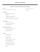
IMPORTANT SAFETY INSTRUCTIONS Important Safety Instructions Warnings and safety instructions appearing in this guide are not meant to cover all possible conditions and situations that may occur. Common sense, caution, and care must be exercised when installing, maintaining, or operating this appliance. Recognize Safety Symbols, Words, and Labels. ! WARNING WARNING - You can be killed or seriously injured if you do not follow these instructions.
UNPACKING YOUR APPLIANCE ! WARNING EXCESSIVE WEIGHT HAZARD Use two or more people to move product. Failure to do so can result in personal injury. Remove Interior Packaging Your appliance has been packed for shipment with all parts that could be damaged by movement securely fastened. Remove internal packing materials and any tape holding internal components in place. The owners manual is shipped inside the product in a plastic bag along with the warranty registration card, and other accessory items.
ELECTRICAL Electrical Connection A grounded 115 volt, 15 amp dedicated circuit is required. Do not remove ground prong This product is factory equipped with a power supply cord that has a three-pronged, grounded plug. It must be plugged into a mating grounding type receptacle in accordance with the National Electrical Code and applicable local codes and ordinances (see figure below).
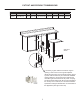
CUTOUT AND PRODUCT DIMENSIONS ROUGH-IN OPENING DIMENSIONS "A" 24" (61 cm) "B" ** 313⁄8" to 323⁄8" (79.7 to 82.2 cm) "C" 24" (61 cm) CABINET DIMENSIONS "D" "E" "F" "G" "H" "J" 237⁄8" (60.7 cm) 311⁄8" to 321⁄8" (79.1 to 81.6 cm) 2323⁄32" (60.2 cm) 2521⁄32" (65.2 cm) 4613⁄32" (117.9 cm) 2511⁄16" (65.
CUTOUT AND PRODUCT DIMENSIONS PRODUCT DATA ELECTRICAL REQUIREMENTS # PRODUCT WEIGHT 115V/60Hz/15A 140 lbs (63.6 kg) "J" "H" "D" "G" "E" 211⁄2" (54.6 cm) Solid door shown "F" ** Minimum rough-in opening required is to be larger than the adjusted height of the cabinet. # A grounded 15 amp dedicated circuit is required. Follow all local building codes when installing electrical and appliance.
INSTALLING YOUR APPLIANCE Select Location The proper location will ensure peak performance of your appliance. We recommend a location where the unit will be out of direct sunlight and away from heat sources. To ensure your product performs to specifications, the recommended installation location temperature range is from 55 to 100°F (13 to 38°C). Front grille screws Cabinet Clearance Ventilation is required from the bottom front of the appliance. Keep this area open and clear of any obstructions.
SIDE-BY-SIDE AND STACKING INSTALLATIONS Side-by-Side Installation Other Site Requirements Units must operate from separate, properly grounded electrical receptacles placed according to each unit's electrical specifications requirements. Hinge-by-Hinge Installation (Mullion) When installing two units hinge-by-hinge, 13/16" (22 mm) is required for integrated models. Additional space may be needed for any knobs, pulls or handles installed.
USING YOUR ELECTRONIC CONTROL Figure 13 Electronic control Control Function Guide Function Notes ON/OFF Adjust Temperature Toggle Between oF / oC Press and release to leave interior light on for Hide Display The oF / o light and display will go dark and remain so until user resets The oF/o Unit will not cool.
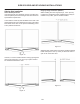
INTERIOR ADJUSTMENTS ! Tall bottle storage area CAUTION Shelf load limit is 35 lbs. Overloading the shelf could result in deflection and risk of injury. Installed shelf tang Shelf support slot Rear tang (hook) on shelf Figure 43 Door storage racks To remove the crisper : Pull out until it stops. Lift up on the front of the pan, and remove it from the frame. Figure 42a To Add or Remove a Shelf Remove stored product from the shelf. Do not try to remove a loaded shelf from the appliance.
CARE AND CLEANING Front Grille Be sure that nothing obstructs the required air flow openings in front of the cabinet. At least once or twice a year, brush or vacuum lint and dirt from the front grille area (see page 8). ! CAUTION SHOCK HAZARD: Disconnect electrical power from the appliance before cleaning with soap and water. Cabinet The painted cabinet can be washed with either a mild soap and water and thoroughly rinsed with clear water. NEVER use abrasive scouring cleaners.
STAINLESS STEEL MAINTENANCE Background Stainless steel does not stain, corrode, or rust as easily as ordinary steel, but it is not stain or corrosion proof. Stainless steels can discolor or corrode if not maintained properly. amount of chromium present. It is this chromium that NOTE Stainless steel products should never be installed, or stored in close proximity to chlorine chemicals.
ENERGY SAVING TIPS The following suggestions will minimize the cost of operating your refrigeration appliance. 1. Do not install your appliance next to a hot appliance (cooker, dishwasher, etc.), heating air duct, or other heat sources. 2. Install product out of direct sunlight. 3. Ensure the front grille vents at front of appliance beneath door are not obstructed and kept clean to allow ventilation for the refrigeration system to expel heat. 4. Plug your appliance into a dedicated power circuit.
EXTENDED NON-USE Vacation/Holiday, Prolonged Shutdown The following steps are recommended for periods of extended non-use: 1. Remove all consumable content from the unit. 2. Disconnect the power cord from its outlet/socket and leave it disconnected until the unit is returned to service. 3. If ice is on the evaporator, allow ice to thaw naturally. 4. Clean and dry the interior of the unit. Ensure all water has been removed from the unit. 5. The door must remain open to prevent formation of mold and mildew.
OBTAINING SERVICE If Service is Required: • If the product is within the first year warranty period please contact your dealer or call Marvel Customer Service at 616.754.5601 for directions on how to obtain warranty coverage in your area. • If the product is outside the first year warranty period, Marvel Customer Service can provide recommendations of service centers in your area. A listing of authorized service centers is also available at www.marvelrefrigeration.
Product Liability Field service technicians are authorized to make an initial assessment in the event of reported damages. If there are any questions about the process involved, the technician should call Marvel for further explanation. While inspecting for defects or installation issues, photos should be taken to document any damages or issues found.
Warranty Claims Units must be registered prior to warranty submittal. The following information defines the parameters for filing a warranty claim: com. A proof of purchase is required. We also accept the following information to update warranty: • Valid serial number needed • Valid model number needed • Claims must be submitted online at www. marvelservice.
Ordering Replacement Parts Parts may be o rdered online at partsformarvel.com Or contact: www.marvelrefrigeration.com (Servicers choose "Login" for service account). Phone Numb er: (616) 754-5601 NOTICE Use only genuine Marvel replacement parts. The use of non-Marvel parts can reduce performance, damage the unit, and void the warranty. Warranty parts will be shipped at no charge after Marvel confirms warranty status. Please provide the model, serial number, part number and part description.
R-600A Specifications & Handling Gloves and Eye Protection must be used. ,., . ���· ' R-600a is considered non-toxic, but is flammable when mixed with air. Keep a dry powder type fire extinguisher in the work area. R-600a is heavier than air, do not allow any leakage/migration to low areas such as basements and stairs. RISK Of FIRE OR EXPLOSION. FLAMMABLE REFRIGERANT USED. TO BE REPAIRED ONLY BY TRAINED SERVICE PERSONNEL DO HOT PUNCTURE REFRIGERANT TUBING RISK Of FIRE OR EXPLOSION.
IA WARNING I Only skilled and well trained service technicians permitted to service R-600a equipped products. R-600A SPECIFICATIONS/LABELING R-600a equipped products are labeled (both the unit and the compressor). R-600a is colorless and odorless. All tools and equipment must be approved for use with R-600a refrigerant. R-600a is considered non-toxic, but is flammable when mixed with air. Local, state and federal laws, standards must be observed along with proper certification and licensing.
Evacuate/reclaim via the piecing pliers to ensure the When re-brazing, the system must be purged with dry system is empty of R-600a before any system work is nitrogen and at least one access point open to the performed. atmosphere. When re-brazing, proper ventilation is required along with constant monitoring for the presence of R600a refrigerant. GAS LEAi< The filter dryer must be replaced any time the sealed system is serviced.
The low side of the refrigeration system (evaporator, Proper ventilation during service is required. compressor and suction line) must be leak tested with the compressor off (equalized pressure). Never apply a torch to a charged R-600a refrigeration system. RECHARGING No air is ever to be allowed inside the refrigeration system (R-600a refrigerant or dry nitrogen only). Use OEM replacement service parts and do not alter the construction of the unit.
System Diagnosis Guide REGRIGERATION SYSTEM DIAGNOSIS GUIDE Capillary Tube Evaporator Wattage Very hot Warm Cold Normal Slightly warm to hot Hot to warm Cool Cold Higher than normal Hot Warm Warm Extremely cold near inlet - Outlet below room temperature Lower than normal Somewhat Warmlower than near room normal vacuum temperature Very hot Top passes Room temperature warm Lower (cool) or colder passes cool (near room temperature) due to liquid Extremely cold near inlet - Outlet below room
MODEL LIST Model # Model 29 *HKR524-***1A 67 MPFZ424, MOFZ224, MLFZ224 30 *HKR524-***2A 31 *HWC315-***2A 68 MPBV424, MPRE424 32 *HWC315-***1A 69 MPWC424 33 *HWC318-***1A 70 MPDR424, MODR224 34 *HWC324-***2A 71 MPBV415 35 *HWC324-***1A 72 MPWC424, MPWC415 36 *HWC515-***2A 73 MPRF424, MPRI424, MLRF224,MLRI224,MORF224 37 *HWC515-***1A 38 *HWC524-***1A 74 MPWD424, MLWD224 39 *HWC524-***2A 75 MPWD424, MLWD224 40 *HWC336-***1A 41 *HBD324-***1A 42 *HBD324-***2A 43 *
Comp/Fan Compressor Compressor Clear Ice, 3 Class **BV315-***1A 01 Control Operation-Service 29 Compressor Compressor Compressor **WD524-***1A **RF124-***1A **RI124-***1A 46 48 52 50 Compressor Compressor **BD524-***1A **WD324-***1A 43 Compressor Compressor **WC336-***1A **BD324-***1A 40 Compressor **WC524-***1A 37 38 41 Compressor Compressor Compressor **WC318-***1A 33 **WC324-***1A Compressor **WC315-***1A 32 **WC515-***1A Compressor **KR524-***1A 27 29 35 Compress
Defrost Outdoor units defrost every 3 hours of compressor runtime for 40 minutes.
Remove Fan and Cover 6. Remove insulating foam from refrigerant line passthrough hole as needed to gain clearance for fan plug. CONVECTION COOLING This unit is equipped with an advanced convection cooling system. Convection cooling stabilizes cabinet temperature, cools product faster and increases energy efficiency. 7. Remove internal shelving. 8. Remove evaporator cover screws. 9.
NOTICE Fan must be oriented to pull air in through lower evaporator cover vents and push air out at fan mounting location. 13. Installation is the reverse of removal. 14. Care must be taken to assure the bottom of the evaporator cover is reinstalled behind the front edge of the train trough. 15. Use sealant gum to seal any openings at rear of unit before replacing rear cover. 16. Reinstall unit taking care to level, space and secure as found.
HOUSEHOLD PRODUCT WARRANTY Marvel Refrigeration (Marvel) Limited Warranty ONE YEAR LIMITED PARTS & LABOR WARRANTY For one year from the date of original purchase, this warranty covers all parts and labor to repair or replace any part of the product that proves to be defective in materials or workmanship. For products installed and used for normal residential use, material cosmetic defects are included in this warranty, with coverage limited to 60 days from the date of original purchase.
www.marvelrefrigeration.com Marvel Refrigeration 1260 E. Van Deinse St. Greenville MI 48838 616.754.5601 All specifications and product designs subject to change without notice. Such revisions do not entitle the buyer to corresponding changes, improvements, additions, replacements or compensation for previously purchased products.