Installation Operation and Maintenance Instructions Ice Machines 15iM (marvel) 25iM (Marvel) 25OiM (Outdoor)
TABLE OF CONTENTS Unpacking your ice machine.................................................. Removing interior packaging............................................... Warranty Registration.......................................................... Installing your ice machine.................................................... Selecting the location......................................................... Outdoor Installation ........................................................... Winterizing .........
UNPACKING YOUR ICE MACHINE Remove Interior Packaging Warranty Registration Your ice machine has been packed for shipment with all parts that could be damaged by movement securely fastened. Remove internal packing materials and any tape holding internal components in place. The owners manual is shipped inside the product in a plastic bag along with the warranty registration card, and other accessory items.
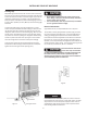
INSTALLING YOUR ICE MACHINE Select Location The proper location will ensure peak performance of your appliance. We recommend a location where the unit will be out of direct sunlight and away from heat sources. To assure your product performs to specifications the recommended installation location temperature range is from 65 to 90°F (18 to 32°C). Front Grille Do not obstruct the front grille. The openings within the front grille allow air to flow through the condenser heat exchanger.
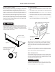
INSTALLING YOUR ICE MACHINE Leveling Legs Adjustable legs at the front and rear corners of the unit should be set so the unit is firmly positioned on the floor and level from side to side and front to back. The overall height of your Marvel refrigerator, depending on the model, may be adjusted from 241/8” (61.3cm) or 333/4” (85.7cm) with the leveling legs turned in, and up to 251/8” (63.8cm) or 343/4” (88.3cm) with the leveling legs extended.
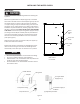
INSTALLING THE WATER SUPPLY Water Supply Observe and follow all local building codes when installing this appliance. Attach the supplied water line adapter (Figure 6) to the water valve inlet on the back of the ice machine (See Figure 5). Be sure the rubber washer is in place in the inlet valve nut. Bend the 1/4” copper tubing to suit your installation being sure not to kink the tubing. Use 1/4” copper tubing for your water supply which is available at any local hardware or plumbing supply store.
USING YOUR ICE MACHINE Ice maker operation Turning on the ice machine • After connecting the water supply, and setting your ice machine in place plug the power cord into the wall receptacle. Then place the switch located in the grille (see Figure 7) to the “ON” position. The temperature control is factory preset, allow the ice maker to run for 24 hours so the interior temperature will stabilize.
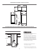
DIMENSIONS FOR MODEL 15IM SOLID DOOR 355/8” (90.5cm) 169/16” (42.1cm) 2311/16” (60.2cm) 147/8” (37.8cm) 241/8” to 251/8” (61.3 to 63.8cm) 1923/32” (50.1cm) 315/16” to 415/16” (10.0 to 12.5cm) 2125/32” (55.3cm) RECOMMENDED ROUGH IN OPENING DIMENSIONS,15IM SOLID DOOR Electrical Requirements: A grounded 115 volt, 15 amp dedicated circuit is required. Power outlet can be located in the back wall behind unit. Add 1” to depth for thickness of plug, or recess outlet 1” into the wall.
DIMENSIONS FOR MODEL 25IM SOLID DOOR 355/8” (90.5cm) 169/16” (42.1cm) 2311/16” (60.2cm) 147/8” (37.8cm) 2125/32” (55.3cm) 333/4” to 343/4” (85.7 to 88.3cm) 3” to 4” (7.6 to 10.2cm) 1923/32” (50.1cm) RECOMMENDED ROUGH IN OPENING DIMENSIONS, 25IM SOLID DOOR Electrical Requirements: A grounded 115 volt, 15 amp dedicated circuit is required. Power outlet can be located in the back wall behind unit. Add 1” to depth for thickness of plug, or recess outlet 1” into the wall.
DIMENSIONS FOR MODEL 25OIM SOLID DOOR 355/8” (90.5cm) 171/32” (43.3cm) 245/32” (61.4cm) 147/8” (37.8cm) 2125/32” (55.3cm) 333/4” to 343/4” (85.7 to 88.3cm) 3” to 4” (7.6 to 10.2cm) 1923/32” (50.1cm) RECOMMENDED ROUGH IN OPENING DIMENSIONS, 25OIM SOLID DOOR Electrical Requirements: A grounded 115 volt, 15 amp dedicated circuit is required. Power outlet can be located in the back wall behind unit. Add 1” to depth for thickness of plug, or recess outlet 1” into the wall.
DIMENSIONS FOR MODEL 25IM SOLID OVERLAY DOOR 355/8” (90.5cm) 137/8” (35.3cm) 2125/32” (55.3cm) 147/8” (37.8cm) 211/32”* (53.4cm) 333/4” to 343/4” (85.7 to 88.3cm) * To face of door without custom panel 3” to 4” (7.6 to 10.2cm) 1923/32” (50.1cm) RECOMMENDED ROUGH IN OPENING DIMENSIONS, 25IM SOLID OVERLAY DOOR Electrical Requirements: A grounded 115 volt, 15 amp dedicated circuit is required. Power outlet can be located in the back wall behind unit.
FULL OVERLAY PANEL INSTALLATION INSTRUCTIONS NOTE For overlay with lock option panel thickness to be 3/4” (19mm) maximum to 5/8” (16mm) minimum. Step 1: Verify door alignment Verify that the door is aligned correctly with the cabinet prior to fabricating the custom panel. Failure to do so may result in mis-alignment of the custom panel with the hinge bracket. The door should be parallel to the sides and top of the refrigerator.
FULL OVERLAY PANEL INSTALLATION INSTRUCTIONS Step 6: Drill panel mounting holes Re-clamp the panel to the door per step 5 and drill the screw pilot holes for attaching the overlay panel to the door. Select the size of the hole from Table A. Be careful not to drill the pilot holes through the overlay panel, (1/2” (12.7mm) deep for 3/4” (19mm) and 5/8” (15.7mm) panels ). Material Type #8 Wood Screw Hardwood 1/8” (3.2mm) Diameter. Pilot Hole Softwood 7/64 (2.8mm) Diameter.
FULL OVERLAY PANEL INSTALLATION INSTRUCTIONS Step 8: Assemble the lock parts Two (2) lock extensions are supplied with the lock. Use the longer extension for a 3/4” thick overlay panel and the shorter one for a 5/8” thick panel. Assemble the lock extension, cam stop washer, spring washer, and set screw to the lock as shown in Figure 12 and 13. Install this assembly into the overlay panel and secure with the retaining nut using a 15mm socket. Make sure the key slot in the lock is vertical.
CARE AND CLEANING Cabinet The painted cabinet can be washed with either a mild soap and water and thoroughly rinsed with clear water. NEVER use abrasive scouring cleaners. Defrosting Instructions 1. 2. Push the rocker switch located in the front grille to the “OFF” position. Remove the ice bucket and place a towel in the lower front area of the ice maker to absorb the defrost water. After defrosting is completed replace the ice bucket and press the rocker switch to the “ON” position. Interior 3.
TROUBLESHOOTING YOUR ICE MACHINE Before You Call for Service If the unit appears to be malfunctioning, read through this manual first. If the problem persists, check the troubleshooting guide below. Locate the problem in the guide and refer to the cause and its remedy before calling for service. The problem may be something very simple that can be solved without a service call. However, it may be required to contact your dealer or a qualified service technician.
TROUBLESHOOTING YOUR ICE MACHINE Problem Unit too warm or too cold inside. Possible Cause Remedy • • Control set too warm or cold Content temperature not stabilized. • • • • Excessive usage or prolonged door openings. Airflow to front grille blocked. • Door gasket not sealing properly. • • Unit not level • • Water line tubing vibration. • • Unit turned off • • • Power cord not plugged in. No power at outlet. • • Moisture collects on outside surface of cabinet.
OBTAINING SERVICE If Service is Required: • • • • • If the product is within the first year warranty period please contact your dealer or call AGA MARVEL Customer Service at 800.223.3900 for directions on how to obtain warranty coverage in your area. If the product is outside the first year warranty period, AGA MARVEL Customer Service can provide recommendations of service centers in your area. A listing of authorized service centers is also available at www.agamarvel.
HOUSEHOLD PRODUCT WARRANTY Entire Product Limited One Year Parts and Labor Warranty AGA MARVEL warrants that it will supply all necessary parts and labor to repair or replace in the end user’s home or office, any component which proves to be defective in material or workmanship, subject to the condition and exclusions stated below, for a period of one year from the date of purchase by the end user.
www.agamarvel.com 1260 E. VanDeinse St. Greenville MI 48838 800.223.3900 41011771-EN Rev S 12/12/12 All specifications and product designs subject to change without notice. Such revisions do not entitle the buyer to corresponding changes, improvements, additions, replacements or compensation for previously purchased products.
Instructions d’installation, d’utilisation et d’entretien Machines à glaçons 15iM (Marvel) 25iM (Marvel) 25OiM (Extérieur)
CONTENU Importantes instructions de sécurité Déballage de votre machine à glaçons.................................... 3 Enlèvement de l’emballage.................................................. 3 Enregistrement de la garantie.............................................. 3 Installation de votre machine à glaçons............................... 4 Choix de l’emplacement....................................................... 4 Installation à l’extérieur........................................................
DÉBALLAGE DE VOTRE RÉFRIGÉRATEUR Enlèvement de l’emballage Enregistrement de la garantie Votre réfrigérateur a été emballé pour l’expédition avec toutes les pièces pouvant être endommagées par le mouvement solidement attachées. Coupez le matériau de fixation en bas du carton, dépliez le carton par le bas et enlevez-le de l’appareil. Enlevez le sac en plastique, les cales d’angle en polystyrène expansé, et toutes les bandes adhésives maintenant la porte fermée et les composants à l’intérieur en place.
INSTALLATION DE VOTRE MACHINE À GLAÇONS Choix de l’emplacement ATTENTION Un bon emplacement assurera une performance de pointe pour votre appareil. Nous recommandons un endroit où l’appareil ne sera pas exposé directement au rayonnement solaire et restera écartée de sources de chauffage. Pour assurer que les performances de votre produit soient au niveau de ses spécifications, la plage de températures recommandée au lieu d’installation sera de 65 à 90°F (18 à 32 °C).
INSTALLATION DE VOTRE MACHINE À GLAÇONS Pieds de mise à niveau ATTENTION Des pieds réglables aux angles avant et arrière de l’armoire doivent être ajustés pour qu’elle soit fermement positionnée au sol et bien d’aplomb, d’un côté à l’autre et d’avant en arrière. La hauteur totale de votre appareil Marvel peut être ajustée entre 333/4” (85,7 cm) quand ses pieds de mise à niveau sont vissés, et 343/4” (88,3 cm) quand ils sont sortis.
BRANCHEMENT DE L’ARRIVÉE D’EAU Alimentation en eau Respectez et observez toutes les normes locales pour l’installation de la machine à glaçons. Fixez l’adaptateur de conduite d’eau fourni (Figure 6) sur l’entrée de la vanne d’eau à l’arrière de la machine à glaçons (Voir la Figure 5). Assurez-vous que la rondelle en caoutchouc est en place dans l’écrou d’entrée de vanne. Formez un tuyau de cuivre de 1/4” en fonction des besoins de votre installation, en prenant soin de ne pas le pincer.
UTILISATION DE VOTRE MACHINE À GLAÇONS Fonctionnement Mise en marche de votre machine à glaçons • Après avoir branché l’alimentation en eau, et mis votre machine à glaçon à sa place, branchez la fiche de son cordon d’alimentation dans une prise secteur murale. Puis placez l’interrupteur placé dans la grille (Voir la Figure 7) en position de marche (ON).
DIMENSIONS POUR PORTE PLEINE DE MODÈLE 15IM 355/8” (90,5 cm) 169/16” (42,1 cm) 2311/16” (60,2cm) 147/8” (37,8 cm) 241/8” à 251/8” (61,3 à 63,8 cm) 1923/32” (50,1 cm) 315/16” à 415/16” (10,0 à 12,5 cm) 2125/32” (55,3 cm) DIMENSIONS BRUTES D’OUVERTURE RECOMMANDÉES POUR PORTE PLEINE DE 15IM ATTENTION Besoins électriques : Un circuit secteur dédié en 115 V supportant 15 A est nécessaire. Une prise avec protection GFCI peut être nécessaire avec les modèles pour extérieur.
DIMENSIONS POUR PORTE PLEINE DE 25IM 355/8” (90,5 cm) 169/16” (42,1 cm) 2311/16” (60,2 cm) 147/8” (37,8 cm) 2125/32” (55,3 cm) 333/4” to 343/4” (85.7 to 88.3cm) 3” to 4” (7.6 to 10.2cm) 1923/32” (50,1 cm) DIMENSIONS BRUTES D’OUVERTURE RECOMMANDÉES POUR PORTE PLEINE DE 25IM ATTENTION Besoins électriques : Un circuit secteur dédié en 115 V supportant 15 A est nécessaire. Une prise avec protection GFCI peut être nécessaire avec les modèles pour extérieur.
DIMENSIONS POUR PORTE PLEINE DE 25OIM 355/8” (90,5 cm) 171/32” (43,3 cm) 245/32” (61,4 cm) 147/8” (37,8 cm) 2125/32” (55,3 cm) 333/4” to 343/4” (85.7 to 88.3cm) 3” to 4” (7.6 to 10.2cm) 1923/32” (50,1 cm) DIMENSIONS BRUTES D’OUVERTURE RECOMMANDÉES POUR PORTE PLEINE DE 25OIM ATTENTION Besoins électriques : Un circuit secteur dédié en 115 V supportant 15 A est nécessaire. Une prise avec protection GFCI peut être nécessaire avec les modèles pour extérieur.
DIMENSIONS POUR PORTE À REVÊTEMENT PLEIN DE 25IM 355/8” (90,5 cm) 137/8” (35,3 cm) 2125/32” (55,3 cm) 147/8” (37,8 cm) 211/32”* (53,4 cm) 333/4” à 343/4” (85,7 à 88,3 cm) * Pour recouvrir une porte sans panneau personnalisé 3” à 4” (7,6 à 10,2 cm) 1923/32” (50,1 cm) DIMENSIONS BRUTES D’OUVERTURE RECOMMANDÉES POUR PORTE À REVÊTEMENT PLEIN DE 25IM ATTENTION Besoins électriques : Un circuit secteur dédié en 115 V supportant 15 A est nécessaire.
INSTRUCTIONS D’INSTALLATION DE PANNEAU DE REVÊTEMENT COMPLET REMARQUE NOTE ATTENTION Pour un revêtement avec option de verrouillage, l’épaisseur de panneau doit faire 3/4” (19 mm) au maximum et 5/8” (16 mm) au minimum. Étape 1 : Vérification de l’alignement de porte Vérifiez que la porte est correctement alignée par rapport à l’armoire avant de fabriquer le panneau sur mesures. Sinon cela peut amener un désalignement du panneau sur mesures avec le support de charnière.
INSTRUCTIONS D’INSTALLATION DE PANNEAU DE REVÊTEMENT COMPLET Étape 6 : Percez les trous de montage du panneau Maintenez à nouveau le panneau sur la porte comme à l’étape précédente et percez les avant-trous de vis, situés dans le canal de joint, afin de fixer le panneau de revêtement à la porte. Choisissez la taille du trou à partir du Tableau B. Veillez à ne pas percer ces avant-trous en traversant le panneau de revêtement, 1/2” (12,7 mm) de profondeur pour des panneaux de 3/4” (19 mm) et 5/8” (15,7 mm).
INSTRUCTIONS D’INSTALLATION DE PANNEAU DE REVÊTEMENT COMPLET Étape 8 : Assemblez les pièces de verrouillage Deux (2) extensions de verrouillage sont fournies avec le verrou. Utilisez l’extension la plus longue pour un panneau de revêtement d’épaisseur 3/4” et la plus courte pour un panneau d’épaisseur 5/8”. Assemblez l’extension de verrouillage, une rondelle d’arrêt de came, une rondelle élastique et une vis de fixation sur le verrou comme montré aux Figures 12 et 13.
ENTRETIEN ET NETTOYAGE Armoire Instructions de dégivrage L’armoire peinte peut se laver avec une solution savonneuse douce, puis soigneusement se rincer à l’eau potable. N’utilisez JAMAIS de produits nettoyants abrasifs. 1. 2. Intérieur 3. Lavez le compartiment intérieur avec une solution savonneuse douce. N’utilisez pas de nettoyant abrasif, de solvant, de produit nettoyant/ polissant ou de détergent non-dilué. Entretien de l’appareil 1. 2. 3. 4.
DÉPANNAGE DE VOTRE MACHINE À GLAÇONS Avant d’appeler pour du service Si l’appareil semble présenter un dysfonctionnement, commencez par bien relire son manuel. Si le problème persiste, consultez le guide de dépannage qui suit. Identifiez le problème dans ce guide et consultez les colonnes de causes et de remèdes avant d’appeler pour du service. Le problème peut être quelque chose de très simple qui peut se résoudre sans demander une intervention de service.
DÉPANNAGE DE VOTRE MACHINE À GLAÇONS Problème L’appareil est trop chaud ou trop froid à l’intérieur. Cause possible • Correction • Le contrôle a une consigne trop chaude ou trop • froide La température du contenu n’est pas encore stabilisée. Utilisation excessive ou ouvertures prolongées • de la porte. Blocage du flux d’air de la grille frontale. • • Défaut d’étanchéité du joint de porte. • • L’appareil n’est pas d’aplomb. • • La vibration vient du tube d’arrivée d’eau.
OBTENTION DE SERVICE Si du service est nécessaire : • • • • • Si le produit est encore dans sa première année de garantie, veuillez appeler le service à la clientèle d’AGA MARVEL au 800.223.3900 pour avoir des instructions sur la façon d’obtenir une couverture sous garantie dans votre secteur. Si le produit est sorti de sa première année de garantie, le service à la clientèle d’AGA MARVEL peut vous fournir des recommandations sur les centres de service de votre secteur.
GARANTIE D’APPAREIL À USAGE DOMESTIQUE Appareil complet Garantie limitée d’un an sur pièces et main-d’œuvre AGA MARVEL garantit qu’il fournira toutes les pièces et la main-d’œuvre nécessaires pour réparer ou remplacer, au domicile ou au bureau de l’utilisateur final, tout composant avéré défectueux du fait des matériaux ou de la main-d’œuvre, en tenant compte des conditions et exclusions décrites plus bas, pendant une période d’une année à compter de la date d’achat par l’utilisateur final.
www.agamarvel.com 1260 E. VanDeinse St. Greenville MI 48838 800.223.3900 41011771-CFR Rév. S 12/12/12 Toutes les spécifications et les conceptions des produits sont sujettes à des changements sans préavis. De telles révisions ne donnent aucun droit pour l’acheteur de produits antérieurs à bénéficier de ces changements, améliorations, ajouts, remplacements, ni de recevoir une compensation.