EN Installation, Operation and Maintenance Instructions FR Instructions d’installation, d’utilisation et d’entretien ES Instrucciones de instalación, operación y mantenimiento Refrigerators Réfrigérateurs Refrigeradores ML15BC ML24BC MA24BC ML24BR MA24BR ML15RA ML24RA MA24RA
CONTENTS Contents: Important Safety Instructions Safety information ...............................................................2 Unpacking your appliance ..................................................3 Warranty registration .....................................................3 Installing your appliance ......................................................4 Cabinet clearances .........................................................4 Leveling the appliance ........................................
UNPACKING YOUR APPLIANCE ! Warranty Registration WARNING It is important you send in your warranty registration card immediately after taking delivery of your appliance or you can register online at www.agamarvel.com. EXCESSIVE WEIGHT HAZARD Use two or more people to move product. Failure to do so can result in personal injury. The following information will be required when registering your appliance.
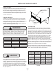
INSTALLING YOUR APPLIANCE Select Location The proper location will ensure peak performance of your appliance. We recommend a location where the unit will be out of direct sunlight and away from heat sources. To ensure your product performs to specifications, the recommended installation location temperature range is from 55 to 100°F (13 to 38°C). Front Grille, keep this area open. Cabinet Clearance Ventilation is required from the bottom front of the appliance.
INSTALLING YOUR APPLIANCE ! WARNING Electrical Shock Hazard Do not remove ground prong • Do not use an extension cord with this appliance. They can be hazardous and can degrade product performance. • This appliance should not, under any circumstances, be installed to an un-grounded electrical supply. • Do not remove the grounding prong from the power cord. (See Figure 3). • Do not use an adapter. (See Figure 4). • Do not splash or spray water from a hose on the appliance.
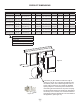
INSTALLING THE ANTI TIP DEVICE FOR FREESTANDING INSTALLATIONS Anti-Tip Bracket WARNING ! • ALL APPLIANCES CAN TIP RESULTING IN INJURY. • INSTALL THE ANTI-TIP BRACKET PACKED WITH THE APPLIANCE. • FOLLOW THE INSTRUCTIONS BELOW 211⁄2" (54.6 cm) Leveling Leg Bottom View of Refrigerator Front of cabinet Figure 7 Anti-Tip Device ! Step by step instructions for locating the position of the bracket: WARNING 1) Decide where you want to place the refrigerator.
INSTALLING THE ANTI TIP DEVICE FOR FREESTANDING INSTALLATIONS NOTE When the floor mounted anti-tip bracket is used the minimum adjusted height of the cabinet is increased by 3 ⁄8" (9 mm). nt o Fro net bi f ca line Sid eo f c Rear Leveling leg ab ine t li ne Screw 211⁄2" (54.
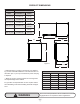
PRODUCT DIMENSIONS ROUGH-IN OPENING DIMENSIONS CABINET DIMENSIONS MODEL "A" "B" "C" "D" "E" "F" "G" "H" "J" ML15**(G) or (S) 15" (38.1 cm) **34" to 35" (86.4 to 88.9 cm) * 147⁄8" (37.8 cm) 333⁄4" to 343⁄4" (85.7 to 88.3 cm) 2323⁄32" (60.2 cm) 2521⁄32" (65.2 cm) 3713⁄32" (95 cm) 1611⁄16" (42.4 cm) ML15**(P) or (F) 15" (38.1 cm) **341⁄4" to 351⁄4" (87 to 89.5 cm) * 147⁄8" (37.8 cm) 34" to 35" (86.4 to 88.9 cm) 227⁄8" (58.1 cm) - 371⁄2" (95.2 cm) 141⁄8" 35.
PRODUCT DIMENSIONS PRODUCT DATA MODEL ELECTRICAL REQUIREMENTS # PRODUCT WEIGHT ML15**(G) or (S) 115V/60Hz/15A 105 lbs (47.7 kg) ML15**(P) or (F) 115V/60Hz/15A 105 lbs (47.7 kg) ML24**(G) or (S) 115V/60Hz/15A 140 lbs (63.6 kg) ML24**(P) or (F) 115V/60Hz/15A 140 lbs (63.6 kg) MA24**(G) or (S) 115V/60Hz/15A 140 lbs (63.6 kg) MA24**(P) or (F) 115V/60Hz/15A 140 lbs ((63.6 kg) "J" "H" "D" "G" "E" 211⁄2" (54.
USING YOUR ELECTRONIC CONTROL Temp Minus keypad On/Off keypad Temp Plus keypad Lights keypad (glass door Lock keypad only) Display Area System Status indicators Figure 12 Electronic single zone control Power Failure ALARM RESET To wake the display press any keypad. A confirm tone will sound, and the current storage compartment temperature will be displayed. Starting your appliance: Plug the appliance power cord into a 115 volt wall outlet.
USING YOUR ELECTRONIC CONTROL Interior display lighting: (Glass door models only) Your appliance is equipped with a dual light level display lighting feature. With the control out of sleep mode press the "Light" keypad once to activate the interior lighting display feature at full illumination. A confirmation tone will sound, and the light bulb "Icon" will illuminate. Pressing the "Light" keypad a 2nd time will dim the lighting to 50%. A 3rd press will deactivate the display lighting feature.
USING YOUR ELECTRONIC CONTROL Alarms: The control will alert you to conditions that could adversely affect the performance of the appliance. Temp • Door Ajar ALARM RESET • Door ajar - If the door is open, or not closed prop- erly, for more than 5-minutes the System Status OK indicator will turn-off, the "Door Ajar" indicator will flash, and a tone will sound every 60 seconds. Additionally, an "ALARM RESET" indicator will be displayed below the "On/Off" keypad.
USING YOUR ELECTRONIC CONTROL Vacation mode: This operating mode can be used to save energy during high cost energy periods, or when you won't be using your appliance for an extended period of time by disabling the lights, alarm tones, and keypad entry tones. Vacation mode also serves as a Sabbath mode, disabling functions and its controls in accordance with the weekly Sabbath and religious holidays observed within the Orthodox Jewish community.
OVERLAY DOOR PANEL INSTALLATION If you purchased an overlay panel model, your unit is equipped with articulated hinges to allow fully integrated built-in installations. Custom panel thicknesses of 5⁄8" (15 mm) and 3⁄4" (18 mm) are accommodated. ! ! WARNING Use extreme caution with the articulated hinges. The hinge is self closing and many pinch points exist prior to built-in installation. Do not remove the cabinet "Z" bracket from the top of the cabinet.
OVERLAY DOOR PANEL INSTALLATION Step 2: Remove the door gasket With the door laying on a flat surface and starting at a corner of the door remove the magnetic door gasket from the interior side of the door, see Figure 15. Set the gasket aside on a flat surface. Overlay panel flush with top of door. There are 10 holes in the gasket retainer extrusions, (3 on each side and 2 at the top and bottom which are used to fasten the panel to the front of the door.
OVERLAY DOOR PANEL INSTALLATION Clearance for screw head, 4 places f po Hinge side of door Figure 16 Left Hand Hinged Door 15" (38.1 cm) wide appliance Clearance for screw head, 4 places Hinge side of door To or do Figure 18 Right Hand Hinged Door 15" (38.1 cm) wide appliance Clearance for hinge 2 places Clearance for hinge 2 places 143⁄4" (37.5 cm) 1" (25.4 mm) diameter counter bore 1⁄4" (6 mm) deep 4 places. 1 ⁄4" (6 mm) Deep 1 143⁄4" (37.5 cm) ⁄4" (6 mm) Deep 47⁄8" 5" (12.7 cm) (12.
OVERLAY DOOR PANEL INSTALLATION r oo d of CAUTION Weight of overlay door panel must not exceed 15 pounds (6.8 kg) for a solid door model or 10 pounds (4.5 kg) for a glass door model. Hinge side of door p To ! 233⁄4" (60.3 cm) ⁄4" (6 mm) Deep 1 do or 233⁄4" (60.3 cm) 1 ⁄4" (6 mm) Deep 13⁄4" (4.4 cm) 13⁄4" (4.4 cm) 13⁄16" (3 cm) of Clearance for hinge at top and bottom Clearance for hinge at top and bottom 14" (35.
OVERLAY DOOR PANEL INSTALLATION Step 4: Assemble the panel to the door The preferred method of attaching the panel to the door is to clamp the panel to the door so it cannot move while drilling the screw pilot holes. Use bar clamps or "C" clamps with pads on the clamping surfaces that will not mar the panel or the door. The custom overlay panel should be flush with the top of the door and centered along the width of the door. See Figure 15a.
OVERLAY DOOR PANEL INSTALLATION Step 5: Assemble lock parts Two (2) lock extensions are provided with the lock. Use the longer extension for 3⁄4" thick overlay panels and the shorter one for 5⁄8" thick overlay panels. Assemble the lock extension, cam stop washer, spring washer, and set screw to the lock as shown in Figure 24 and 26. Counter bore lock hole on back side.
OVERLAY DOOR PANEL INSTALLATION Screw Cam Spring washer Brass extension (2 lengths provided Retainer nut Cam stop washer Key Lock Set screw Figure 26 Step 7: Install the door Carefully open the top and bottom hinges on the door being careful as there are many pinch points. Place the hinges over the 4 screws in the cabinet, 2 at the top and 2 at the bottom and slide the door into position. Tighten the 4 hinge screws with a phillips screwdriver. (See Figures 13 and 13a).
SHELVING CONFIGURATIONS Loading Tips and Suggestions Your appliance is equipped with a cantilever shelf system which provides maximum adjust ability and customizing of the shelving arrangements listed below. Beverage Refrigerator: 24" (61 cm) Wide Models: Shown with a glass door. Figure 30. (1) half width flat glass cantilever shelf. (See Figure 35). (1) wine cutout and flat glass cantilever shelf. (See Figure 37). (1) frame and flat glass crisper cover.
SHELVING CONFIGURATIONS Refrigerator: 24" (61 cm) Wide Models: Shown with a solid door with door racks. Figure 33. (1) half width flat glass cantilever shelf. (See Figure 36). (1) frame and slumped glass cantilever shelf. (1) frame and flat glass crisper cover. (1) roll-out crisper pan. (1) full width door storage rack. (1) half width door storage rack.
SHELVING CONFIGURATIONS To Add or Remove a Shelf Installed shelf tang Shelf support slot Remove stored product from the shelf. Do not try to remove a loaded shelf from the appliance. Grasp the shelf front with both hands, rotate the front upward and lift out. (See Figure 39b). To install a shelf insert the shelf in the appliance and insert the top hooks into the shelf support slots and drop the shelf down so the hooks drop over the bottom of the slots.
CARE AND CLEANING AND ENERGY SAVING TIPS Front Grille Be sure that nothing obstructs the required air flow openings in front of the cabinet. At least once or twice a year, brush or vacuum lint and dirt from the front grille area (see page 4). ! CAUTION SHOCK HAZARD: Disconnect electrical power from the appliance before cleaning with soap and water. Cabinet The painted cabinet can be washed with either a mild soap and water and thoroughly rinsed with clear water. NEVER use abrasive scouring cleaners.
DOOR ALIGNMENT AND OBTAINING SERVICE Door alignment for solid and glass door models: The door should be parallel to the sides and top of the appliance. If alignment is necessary the door may be adjusted by loosening the 2 screws which secure the door adjustment bracket on the bottom of the door (see Figure 40a) and adjusting the door side to side. Use a 5⁄32” allen wrench for this procedure. (See Figure 40 below). When finished aligning the door, tighten the screws securely.
TROUBLESHOOTING Before You Call for Service Problem Appliance not cold enough WARNING ! If the appliance appears to be malfunctioning, read through this manual first. If the problem persists, check the troubleshooting guide below. Locate the problem in the guide and refer to the cause and its remedy before calling for service. The problem may be something very simple that can be solved without a service call. However, it may be required to contact your dealer or a qualified service technician.
HOUSEHOLD PRODUCT WARRANTY Entire Product Limited One Year Parts and Labor Warranty Parts or Service Not Supplied or Designated by AGA MARVEL AGA MARVEL warrants that it will supply all necessary parts and labor to repair or replace in the end user’s home or office, any component which proves to be defective in material or workmanship, subject to the condition and exclusions stated below, for a period of one year from the date of purchase by the end user.
www.agamarvel.com 1260 E. VanDeinse St. Greenville MI 48838 800.223.3900 41013316-EN Rev G 12/10/14 All specifications and product designs subject to change without notice. Such revisions do not entitle the buyer to corresponding changes, improvements, additions, replacements or compensation for previously purchased products.
EN Installation, Operation and Maintenance Instructions FR Instructions d’installation, d’utilisation et d’entretien ES Instrucciones de instalación, operación y mantenimiento Refrigerators Réfrigérateurs Refrigeradores ML15BC ML24BC MA24BC ML24BR MA24BR ML15RA ML24RA MA24RA
CONTENU Contenu : Importantes instructions de sécurité Informations de sécurité.......................................................2 Déballage de votre appareil ..................................................3 Enregistrement de la garantie ......................................3 Installation de votre appareil ..............................................4 Dégagements par rapport à l’armoire .............................4 Mise à niveau de l’appareil .............................................
DÉBALLAGE DE VOTRE APPAREIL ! Enregistrement de la garantie AVERTISSEMENT Il est important que vous postiez votre carte de garantie immédiatement après avoir pris livraison de votre réfrigérateur. AVERTISSEMENT RISQUE DE POIDS EXCESSIF Les informations suivantes seront nécessaires au moment de l’enregistrement de votre appareil : Numéro de service Numéro de série Date d’achat Nom et adresse du revendeur Utilisez deux personnes ou plus pour déplacer le produit. Sinon vous pourriez vous blesser.
INSTALLATION DE VOTRE APPAREIL Choix de l’emplacement Un bon emplacement assurera une performance de pointe pour votre appareil. Nous recommandons un endroit où l’appareil ne sera pas exposé directement au rayonnement solaire et restera écarté de sources de chauffage. Pour assurer que les performances de votre produit soient au niveau de ses spécifications, la plage de températures recommandée au lieu d’installation sera de 55 à 100°F (13 à 38 °C). Grille frontale, gardez cette zone dégagée.
INSTALLATION DE VOTRE APPAREIL ! AVERTISSEMENT Risque de commotion électrique N’enlevez pas la borne de terre de la fiche du cordon secteur. • N’utilisez pas de rallonge secteur avec cet appareil. Cela peut être dangereux et peut affecter la performance du produit. • Cet appareil ne doit sous aucun prétexte être installé sur une alimentation électrique sans liaison de terre. • N’enlevez pas la borne de terre de la fiche du cordon secteur. (Voyez la Figure 3).
INSTALLATION DU DISPOSITIF ANTI-BASCULEMENT POUR DES INSTALLATIONS AUTONOMES ! Dispositif anti-basculement AVERTISSEMENT • TOUS LES APPAREILS PEUVENT BASCULER.
INSTALLATION DU DISPOSITIF ANTI-BASCULEMENT POUR DES INSTALLATIONS AUTONOMES REMARQUE Quand la ferrure anti-basculement fixée au sol est utilisée, la hauteur minimale ajustée de l’armoire est augmentée de 3 ⁄8 po (9 mm).
DIMENSIONS DU PRODUIT DIMENSIONS D’OUVERTURE BRUTE DIMENSIONS D’ARMOIRE MODÈLE «A» «B» «C» «D» «E» «F» «G» «H» «J» ML15**(G) ou (S) 15 po (38,1 cm) **34 po à 35 po (86,4 à 88,9 cm) * 147⁄8 po (37,8 cm) 333⁄4 po à 343⁄4 po (85,7 à 88,3 cm) 2323⁄32 po (60,2 cm) 2521⁄32 po (65,2 cm) 3713⁄32 po (95 cm) 1611⁄16 po (42,4 cm) ML15**(P) ou (F) 15 po (38,1 cm) **341⁄4 po à 351⁄4 po (87 à 89,5 cm) * 147⁄8 po (37,8 cm) 34 po à 35 po (86,4 à 88,9 cm) 227⁄8 po (58,1 cm) - 371⁄2 po (95,2 cm
DIMENSIONS DU PRODUIT DONNÉES DE PRODUIT MODÈLE BESOINS ÉLECTRIQUES # POIDS DU PRODUIT ML15**(G) ou (S) 115V/60Hz/15A 105 lb (47,7 kg) ML15**(P) ou (F) 115V/60Hz/15A 105 lb (47,7 kg) ML24**(G) ou (S) 115V/60Hz/15A 140 lb (63,6 kg) ML24**(P) ou (F) 115V/60Hz/15A 140 lb (63,6 kg) MA24**(G) ou (S) 115V/60Hz/15A 140 lb (63,6 kg) MA24**(P) ou (F) 115V/60Hz/15A 140 lb ((63,6 kg) «J» «H» «D» «G» «E» 211⁄2 po (54,6 cm) Figure 11 «F» * La dimension en profondeur de l’ouverture brute peut va
UTILISATION DE VOTRE COMMANDE ÉLECTRONIQUE Diminution Marche/ de température Arrêt Augmentation de température Zone d’affichage Allumage d’éclairage (porte en verre seulement) Verrouillage des touches Indicateur de statut du système Figure 12 Commandes électroniques Power Failure Pour activer l’affichage, appuyez sur n’importe quelle touche. Un signal sonore de confirmation retentira, et la température actuelle du compartiment de conservation sera affichée.
UTILISATION DE VOTRE COMMANDE ÉLECTRONIQUE Éclairage intérieur de présentation : (Modèles à porte vitrée uniquement). Votre appareil est équipé d’un dispositif d’éclairage de présentation à deux niveaux d’intensité. Avec la commande électronique sortie du mode veille, appuyez sur la commande d’éclairage (symbôle d'ampoule) pour activer l’éclairage intérieur de présentation à pleine intensité. Une tonalité de confirmation va retentir, et l’icône d’ampoule d’éclairage va s’allumer.
UTILISATION DE VOTRE COMMANDE ÉLECTRONIQUE Alertes : La commande va vous alerter en cas de conditions pouvant nuire à la performance de l’appareil. Temp • Door Ajar ALARM RESET • Porte entrouverte - Si la porte reste ouverte ou incorrectement fermée, pendant plus de 5 minutes, l’indicateur de statut de système OK va s’éteindre, l’indicateur de porte entrouverte (Door Ajar) va clignoter et une tonalité va retentir toutes les 60 secondes.
UTILISATION DE VOTRE COMMANDE ÉLECTRONIQUE Mode de vacances : Ce mode de fonctionnement peut être utilisé pour économiser de l’énergie durant les périodes où elle est la plus coûteuse, ou si vous n’utilisez pas votre appareil pendant une période prolongée, en désactivant ses éclairages, tonalités d’alerte, et sonorités d’actionnement des commandes.
INSTALLATION DE PANNEAU DE REVÊTEMENT DE PORTE Si vous avez acheté un modèle à panneau de revêtement, votre réfrigérateur est équipé de charnières articulées pour permettre des installations complètement encastrées. Des épaisseurs de panneau de 5⁄8 po (15 mm) et 3⁄4 po (18 mm) sont acceptées. ! Utilisez une extrême prudence avec les charnières articulées. La charnière se referme toute seule et il existe de nombreux points de pinçage avant l’installation encastrée.
INSTALLATION DE PANNEAU DE REVÊTEMENT DE PORTE Étape 2 : Dépose du joint de porte Avec la porte reposant sur une surface plane, et en partant d’un des ses angles, ôtez le joint de porte magnétique de la face intérieure de la porte (Voyez la Figure 15). Mettez de côté ce joint sur une surface plane. Panneau de revêtement aligné avec le haut de la porte.
INSTALLATION DE PANNEAU DE REVÊTEMENT DE PORTE ut de po rte ut Ha Côté charnières de la porte Dégagement pour tête de vis, 4 emplacements Figure 16 Porte à charnières à gauche Appareil de largeur 15 po (38,1 cm) e ort p de Dégagement pour tête de vis, 4 emplacements Côté charnières de la porte Ha Figure 18 Porte à charnières à droite Appareil de largeur 15 po (38,1 cm) Dégagement pour charnière, 2 emplacements 143⁄4 po (37,5 cm) Dégagement pour charnière, 2 emplacements ⁄4 po (6 mm) 1 ⁄4
INSTALLATION DE PANNEAU DE REVÊTEMENT DE PORTE d Le poids du revêtement de porte ne doit pas dépasser 15 lb (6,8 kg) pour un modèle à porte pleine, ou 10 lb (4,5 kg) pour un modèle à porte vitrée.
INSTALLATION DE PANNEAU DE REVÊTEMENT DE PORTE Étape 4 : Assemblez le panneau sur la porte La méthode préférée pour fixer le panneau sur la porte est de le tenir dessus par serre-joints pour éviter tout déplacement durant le perçage d’avant-trous. Utilisez des serre-joints à barre ou en «C» avec des tampons sur les surfaces à serrer pour ne pas marquer le panneau de revêtement ou la porte.
INSTALLATION DE PANNEAU DE REVÊTEMENT DE PORTE Étape 5 : Montez les pièces de verrou Deux (2) extensions de verrouillage sont fournies avec le verrou. Utilisez l’extension la plus longue pour un panneau de revêtement d’épaisseur 3⁄4 po et la plus courte pour un panneau d’épaisseur 5⁄8 po. Assemblez l’extension de verrouillage, une rondelle d’arrêt de came, une rondelle élastique et une vis de fixation sur le verrou comme montré aux Figures 24 et 26.
INSTALLATION DE PANNEAU DE REVÊTEMENT DE PORTE Came Rondelle élastique Rallonge en laiton (2 tailles fournis) Écrou de retenue Clé Verrou Vis Vis de réglage Rondelle d'arrêt de came Figure 26 Étape 7 : Installez la porte Ouvrez soigneusement les charnières du haut et du bas sur la porte en vous méfiant des nombreux points de pinçage. Placez les charnières par-dessus les 4 vis dans l’armoire, 2 en haut et 2 en bas, et glissez la porte en position.
CONFIGURATIONS DE ÉTAGÈRES Conseils et suggestions pour le chargement Votre réfrigérateur est équipé d’un système de étagères en porteà-faux qui procure une capacité maximale d’ajustement et une personnalisation des arrangements comme c’est montré plus loin. Stockage de boissons : Appareils de largeur 15 po (38,1 cm) : Réfrigération de boissons : Appareils de largeur 24 po (61 cm) : Montré avec une porte vitrée en Figure 30 (1) étagère en porte-à faux, demi-largueur en verre (Voyez la Figure 35).
CONFIGURATIONS DE ÉTAGÈRES Réfrigérateur : Appareils de largeur 24 po (61 cm) : Montré avec une porte pleine équipée de balconnets en Figure 33. (1) étagère en porte-à faux, demi-largueur en verre (Voyez la Figure 36). (1) étagère en porte-à faux, encadrement et verre bombé (1) couvercle de bac à légumes, encadrement et verre (1) bac à légumes coulissant (1) rangement de porte pleine largeur. (1) rangement de porte demi-largeur.
CONFIGURATIONS DE ÉTAGÈRES ! Pour ajouter ou enlever une étagère ATTENTION Assurez-vous que votre étagères en porte-à-faux est bien en place sur les supports en appuyant dessus avant de la charger. Fente de support de étagère Enlevez les produits qui étaient entreposés sur la étagère. N’essayez pas d’enlever une étagère du réfrigérateur restée chargée. Prenez le devant de la étagère des deux mains, faites pivoter son avant vers le haut et enlevez-la (Voyez la Figure 39b).
CONSEILS POUR L’ÉCONOMIE D’ÉNERGIE, L’ENTRETIEN ET LE NETTOYAGE Grille frontale Assurez-vous que rien n’obstrue les ouvertures pour flux d’air requises à l’avant de l’armoire Au moins une à deux fois par an, chassez par brossage ou par aspiration les peluches et les saletés dans la zone de la grille avant (Voyez en page 4). ! ATTENTION RISQUE DE COMMOTION ÉLECTRIQUE : Débranchez l’alimentation secteur de l’appareil avant de le nettoyer à l’eau savonneuse.
ALIGNEMENT DE PORTE ET OBTENTION DE SERVICE Alignement de porte pour modèles à porte pleine et vitrée : La porte doit être parallèle avec les côtés et le dessus de l’armoire. Si un alignement est nécessaire, la porte peut être ajustée en desserrant les deux vis qui maintiennent la cornière de réglage de porte en bas de la porte (Voyez la Figure 40a), et en opérant un réglage latéral de la porte. Utilisez une clé Allen de 5 ⁄32 po pour cette procédure (Voir la Figure 40 ci-dessous).
DÉPANNAGE Avant d’appeler pour du service Problème L’appareil ne produit pas assez de froid AVERTISSEMENT ! Si l’appareil semble présenter un dysfonctionnement, commencez par bien relire son manuel. Si le problème persiste, consultez le guide de dépannage qui suit. Identifiez le problème dans ce guide et consultez les colonnes de causes et de remèdes avant d’appeler pour du service. Le problème peut être quelque chose de très simple qui peut se résoudre sans demander une intervention de service.
GARANTIE DE PRODUIT À USAGE DOMESTIQUE Produit complet Garantie limitée d’un an sur pièces et main-d’œuvre Pièces ou service Non fourni ou désigné par AGA MARVEL Les garanties qui précèdent ne s’appliquent pas non plus si : AGA MARVEL garantit qu’il fournira toutes les pièces et la maind'œuvre nécessaires pour réparer ou remplacer, au domicile ou au bureau de l'utilisateur final, tout composant avéré défectueux du fait des matériaux ou de la main-d’œuvre, en tenant compte des conditions et exclusions déc
www.agamarvel.com 1260 E. VanDeinse St. Greenville MI 48838 800.223.3900 41013316-FR Rév. G 12/10/14 Toutes les spécifications et les conceptions des produits sont sujet à des changements sans préavis. De telles révisions ne donnent aucun droit pour l’acheteur de produits antérieurs à bénéficier de ces changements, améliorations, ajouts, remplacements, ni de recevoir une compensation.
EN Installation, Operation and Maintenance Instructions FR Instructions d’installation, d’utilisation et d’entretien ES Instrucciones de instalación, operación y mantenimiento Refrigerators Réfrigérateurs Refrigeradores ML15BC ML24BC MA24BC ML24BR MA24BR ML15RA ML24RA MA24RA
ÍNDICE Índice: Instrucciones importantes de seguridad Información de seguridad...............................................................2 Desembalaje de su artefacto..........................................................3 Registro de garantía..................................................................3 Instalación de su artefacto.............................................................4 Espacios libres alrededor del gabinete.....................................4 Nivelación del artefacto.
DESEMBALAJE DE SU ARTEFACTO ! Registro de garantía ADVERTENCIA Es importante que envíe su tarjeta de registro de la garantía inmediatamente después de haber recibido su artefacto; también puede registrarlo a través de Internet en la página www.agamarvel.com. RIESGO DE PESO EXCESIVO Se necesitan dos o más personas para mover el producto. Si no se procede así, pueden producirse lesiones personales.
INSTALACIÓN DE SU ARTEFACTO Selección de la ubicación La ubicación adecuada asegurará el desempeño óptimo de su artefacto. Recomendamos una ubicación en la que la unidad esté a cubierto de la luz solar directa y lejos de fuentes de calor. Para asegurar que su producto funcione de acuerdo con las especificaciones, el rango de temperaturas recomendado para la ubicación de instalación es de 55 a 100º F (de 13 a 38º C). Rejilla frontal: mantenga esta área abierta.
INSTALACIÓN DE SU ARTEFACTO ! ADVERTENCIA Peligro de choque eléctrico No quite la clavija de puesta a tierra del cordón de alimentación eléctrica. • No utilice cordones de extensión con este artefacto. Pueden ser peligrosos, y pueden degradar el funcionamiento del producto. • Este artefacto no debe conectarse en ninguna circunstancia a un suministro eléctrico sin conexión a tierra. • No quite la clavija de puesta a tierra del cordón de alimentación eléctrica. (vea la Figura 3). • No use un adaptador.
INSTALACIÓN DEL DISPOSITIVO ANTIVUELCO PARA INSTALACIONES AUTOSOSTENIDAS ! Soporte antivuelco ADVERTENCIA • TODOS LOS APARATOS SE PUEDEN VOLCAR. SE PUEDEN PRODUCIR LESIONES. • INSTALE EL SOPORTE ANTIVUELCO EMBALADO CON LA UNIDAD.
INSTALACIÓN DEL DISPOSITIVO ANTIVUELCO PARA INSTALACIONES AUTOSOSTENIDAS NOTA Cuando se utiliza el soporte antivuelco montado en el piso, la altura mínima ajustable del gabinete aumenta en 3⁄8" (9 mm).
DIMENSIONES DEL PRODUCTO DIMENSIONES DE LA ABERTURA DE INSTALACIÓN pulgadas (cm) DIMENSIONES DEL GABINETE pulgadas (cm) MODELO "A" "B" "C" "D" "E" "F" "G" "H" "J" ML15**(G) o (S) 15" (38,1 cm) **34" a 35" (86,4 a 88,9 cm) * 147⁄8" (37,8 cm) 333⁄4" a 343⁄4" (85,7 a 88,3 cm) 2323⁄32" (60,2 cm) 2521⁄32" (65,2 cm) 3713⁄32" (95 cm) 1611⁄16" (42,4 cm) ML15**(P) o (F) 15" (38,1 cm) **341⁄4" a 351⁄4" (87 a 89,5 cm) * 147⁄8" (37,8 cm) 34" a 35" (86,4 a 88,9 cm) 227⁄8" (58,1 cm) - 371⁄2
DIMENSIONES DEL PRODUCTO DATOS DEL PRODUCTO MODELO REQUISITOS ELÉCTRICOS # PESO DEL PRODUCTO ML15**(G) o (S) 115 V / 60 Hz / 15 A 105 lbs (47,7 kg) ML15**(P) o (F) 115 V / 60 Hz / 15 A 105 lbs (47,7 kg) ML24**(G) o (S) 115 V / 60 Hz / 15 A 140 lbs (63,6 kg) ML24**(P) o (F) 115 V / 60 Hz / 15 A 140 lbs (63,6 kg) MA24**(G) o (S) 115 V / 60 Hz / 15 A 140 lbs (63,6 kg) MA24**(P) o (F) 115 V / 60 Hz / 15 A 140 lbs ((63,6 kg) "J" "H" "D" "G" "E" 211⁄2" (54,6 cm) Figura 11 "F" * La dimen
USO DE SU CONTROL ELECTRÓNICO Tecla Tecla para Tecla para bajar “Encendido / subir la la temperatura Apagado” temperatura Tecla “Luces” (solo puerta de Tecla “Bloqueo” vidrio) Pantalla Indicadores de estado del sistema Figura 12 Control electrónico para una sola zona Power Failure ALARM RESET Para activar la pantalla, pulse cualquier tecla. Sonará un tono audible de confirmación y aparecerá la temperatura actual del compartimiento de almacenamiento.
USO DE SU CONTROL ELECTRÓNICO Iluminación interior: (solo modelos con puerta de vidrio) Su artefacto está equipado con una función que permite escoger entre dos niveles de iluminación interior. Con el control fuera del modo de espera, pulse la tecla “Luces” para activar la iluminación interior en el nivel máximo. Sonará un tono de confirmación y se encenderá el indicador con el ícono de una bombilla. Si pulsa nuevamente la tecla “Luces”, la iluminación se atenuará en un 50%.
USO DE SU CONTROL ELECTRÓNICO Alarmas: El control emitirá un aviso cuando las condiciones podrían afectar negativamente al rendimiento del artefacto. Temp • Door Ajar ALARM RESET • Puerta entreabierta: si la puerta está abierta o está mal cerrada durante más de 5 minutos, el indicador de sistema OK se apagará y comenzará a parpadear el indicador “Puerta entreabierta” acompañado de un tono audible cada 60 segundos.
USO DE SU CONTROL ELECTRÓNICO Modo Vacaciones: Este modo de operación se puede utilizar para ahorrar energía mediante la desactivación de las luces, los tonos de alarma y los tonos de entrada de teclado durante los períodos en los que el costo de la energía es elevado, o cuando el artefacto no será utilizado durante un tiempo prolongado.
INSTALACIÓN DEL PANEL DE PUERTA DECORATIVO Si ha comprado un modelo con panel decorativo, su unidad estará equipada con bisagras articuladas que permiten una instalación totalmente empotrada. La unidad admite paneles de 5⁄8" (15 mm) y 3⁄4" (18 mm) de espesor. ! ! ADVERTENCIA Tenga mucho cuidado con las bisagras articuladas. La bisagra es de cierre automático y existen muchos puntos que podrían pellizcar sus manos antes de la instalación empotrada.
INSTALACIÓN DEL PANEL DE PUERTA DECORATIVO Paso 2: desmonte la junta de la puerta. Coloque la puerta sobre una superficie plana y, comenzando desde una esquina de la puerta, retire la junta magnética del lado interior de la puerta (vea la Figura 15). Deje la junta a un lado sobre una superficie plana. Panel decorativo a tope con la parte superior de la puerta.
INSTALACIÓN DEL PANEL DE PUERTA DECORATIVO Figura 16 Puerta abisagrada a la izquierda para artefacto de 15" (38,1 cm) de ancho. Lado de las bisagras de la puerta Lado de las bisagras de la puerta Espacio libre para la cabeza del tornillo (4 lugares) r rio pe u s rta e rte Pa la pu e d Espacio libre para la cabeza del tornillo (4 lugares) Figura 18 Puerta abisagrada a la derecha para artefacto de 15" (38,1 cm) de ancho.
INSTALACIÓN DEL PANEL DE PUERTA DECORATIVO PRECAUCION ! El peso del panel decorativo de la puerta no debe exceder de 15 libras (6,8 kg) para un modelo con puerta maciza, o de 10 libras (4,5 kg) para un modelo con puerta de vidrio.
INSTALACIÓN DEL PANEL DE PUERTA DECORATIVO Paso 4: monte el panel en la puerta. MODELO El método preferido para fijar el panel a la puerta es sujetarlo con pinzas para que no pueda moverse al perforar los agujeros para guía de los tornillos. Utilice sargentos de carpintero o pinzas tipo "C" con almohadillas en las superficies de sujeción para no arruinar el panel ni la puerta.
INSTALACIÓN DEL PANEL DE PUERTA DECORATIVO Paso 5: La cerradura se entrega con dos (2) extensiones. Utilice la más larga para paneles decorativos de 3⁄4" de espesor y la más corta para paneles decorativos de 5⁄8" de espesor. Monte la extensión de la cerradura, la arandela de tope de la leva, la arandela de presión y el tornillo prisionero en la cerradura, como se ilustra en las Figuras 24 y 26. Agujero avellanado para cerradura en la parte posterior. Tornillo n.
INSTALACIÓN DEL PANEL DE PUERTA DECORATIVO Leva Arandela de presión extensión de latón (2 longitudes de siempre) Retención Llave Cerradura Tornillo Arandela de tope de la leva Tornillo prisionero Figura 26 Paso 7: instale la puerta. Abra con cuidado las bisagras superior e inferior de la puerta pues hay muchos puntos que pueden pellizcarle la mano. Coloque las bisagras en los 4 tornillos del gabinete, 2 en la parte superior y 2 en la parte inferior y deslice la puerta en su posición.
CONFIGURACIONES DE ESTANTES Consejos y sugerencias para cargar el refrigerador Su artefacto está equipado con un sistema de estantes en voladizo que ofrece muchas posibilidades de ajuste y se adapta a distintas disposiciones de estantes, enumeradas a continuación. Centro de bebidas: Modelos de 15" (38,1 cm) de ancho: Ilustrado con una puerta de vidrio (vea la Figura 28). Refrigerador de bebidas: Modelos de 24" (61 cm) de ancho: Ilustrado con una puerta de vidrio (vea la Figura 30).
CONFIGURACIONES DE ESTANTES Refrigerador: Modelos de 24" (61 cm) de ancho: Ilustrado con una puerta maciza con gavetas en la puerta (vea la Figura 33). (1) estante en voladizo con vidrio plano, medio ancho (vea la Figura 36). (1) estante en voladizo con marco y vidrio plano derretido. (1) cubierta para alimentos frescos compuesta por marco y vidrio plano. (1) bandeja para alimentos frescos deslizable sobre rodillos. (1) gaveta de almacenamiento a todo lo ancho de la puerta.
CONFIGURACIONES DE ESTANTES ! Para agregar o desmontar un estante, proceda como se indica a continuación PRECAUCION Antes de cargar el estante en voladizo presiónelo hacia abajo para verificar que está bien asegurado en los soportes. Ranura de soporte del estante Gancho de un estante instalado Retire los productos almacenados del estante. No trate de desmontar del artefacto un estante cargado.
CUIDADOS Y LIMPIEZA - CONSEJOS PARA AHORRAR ENERGÍA Rejilla frontal Verifique que nada obstruye el flujo de aire requerido en las aberturas delanteras del gabinete. Cepille o limpie con una aspiradora las pelusas y suciedad acumuladas en las aberturas de la rejilla al menos una o dos veces al año (vea la página 4). ! PRECAUCION PELIGRO DE CHOQUE ELÉCTRICO: Desconecte la alimentación eléctrica del artefacto antes de limpiarlo con agua y jabón.
ALINEACIÓN DE LA PUERTA Y SOLICITUD DE SERVICIO TÉCNICO Para alinear la puerta, ya sea maciza o de vidrio, proceda como se indica a continuación: La puerta debe estar paralela a los laterales y a la parte superior del artefacto. En caso de que la puerta necesite ser alineada, afloje los 2 tornillos que aseguran el soporte de ajuste de la puerta en su parte inferior (vea la Figura 40a) y ajuste la puerta de lado a lado. Utilice una llave allen de 5⁄32” para este procedimiento (vea la Figura 40 abajo).
LOCALIZACIÓN DE FALLAS Antes de llamar al servicio técnico siga estos consejos ! Si el artefacto parece estar funcionando mal, lea primero este manual. Si el problema persiste, vea la guía de localización de fallas incluida a continuación. Antes de llamar al servicio técnico, localice el problema en la guía y consulte su causa y su solución. Tal vez el problema sea algo muy simple que puede resolverse sin llamar al servicio técnico.
GARANTÍA DE PRODUCTOS ELECTRODOMÉSTICOS Para el producto completo Un año de garantía limitada sobre piezas y mano de obra del producto completo Piezas o servicios No provistos o designados por AGA MARVEL Las garantías indicadas tampoco serán de aplicación si: AGA MARVEL garantiza el suministro de todas las piezas y la mano de obra necesarias para reparar o reemplazar en el domicilio u oficina del usuario cualquier componente en el que se haya comprobado la presencia de defectos, sea por materiales o por m
www.agamarvel.com 1260 E. VanDeinse St. Greenville MI 48838 800.223.3900 41013316-SP Rev G 12/10/14 Todas las especificaciones y diseños del producto están sujetos a cambios sin aviso previo. Las revisiones del producto no le otorgan al comprador el derecho a cambios, mejoras, accesorios adicionales, reemplazos o compensaciones por los productos previamente comprados.