EN Installation, Operation and Maintenance Instructions FR Instructions d’installation, d’utilisation et d’entretien ES Instrucciones de instalación, operación y mantenimiento Freezers Congélateurs Congeladors ML24FA
CONTENTS Contents: Important Safety Instructions Safety information ...............................................................2 Unpacking your appliance ..................................................3 Warranty registration .....................................................3 Installing your appliance ......................................................4 Cabinet clearances .........................................................4 Leveling the appliance ........................................
UNPACKING YOUR APPLIANCE ! Warranty Registration WARNING It is important you send in your warranty registration card immediately after taking delivery of your appliance or you can register online at www.agamarvel.com. EXCESSIVE WEIGHT HAZARD Use two or more people to move product. Failure to do so can result in personal injury. The following information will be required when registering your appliance.
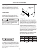
INSTALLING YOUR APPLIANCE Select Location The proper location will ensure peak performance of your appliance. We recommend a location where the unit will be out of direct sunlight and away from heat sources. To ensure your product performs to specifications, the recommended installation location temperature range is from 55 to 100°F (13 to 38°C). Front Grille, keep this area open. Cabinet Clearance Ventilation is required from the bottom front of the appliance.
INSTALLING YOUR APPLIANCE ! WARNING Electrical Shock Hazard Do not remove ground prong • Do not use an extension cord with this appliance. They can be hazardous and can degrade product performance. • This appliance should not, under any circumstances, be installed to an un-grounded electrical supply. • Do not remove the grounding prong from the power cord. (See Figure 3). • Do not use an adapter. (See Figure 4). • Do not splash or spray water from a hose on the appliance.
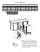
INSTALLING THE ANTI TIP DEVICE FOR FREESTANDING INSTALLATIONS Anti-Tip Bracket WARNING ! • ALL APPLIANCES CAN TIP RESULTING IN INJURY. • INSTALL THE ANTI-TIP BRACKET PACKED WITH THE APPLIANCE. • FOLLOW THE INSTRUCTIONS BELOW 211⁄2" (54.6 cm) Leveling Leg Bottom View of Freezer Front of cabinet Figure 7 Anti-Tip Device ! Step by step instructions for locating the position of the bracket: WARNING 1) Decide where you want to place the freezer.
INSTALLING THE ANTI TIP DEVICE FOR FREESTANDING INSTALLATIONS NOTE When the floor mounted anti-tip bracket is used the minimum adjusted height of the cabinet is increased by 3 ⁄8" (9 mm). nt o Fro net bi f ca line Sid eo f c Rear Leveling leg ab ine t li ne Screw 211⁄2" (54.
PRODUCT DIMENSIONS ROUGH-IN OPENING DIMENSIONS CABINET DIMENSIONS MODEL "A" "B" "C" "D" "E" "F" "G" "H" "J" ML24FA(S) 24" (61 cm) **34" to 35" (86.4 to 88.9 cm) 24" (61 cm) 237⁄8" (60.7 cm) 333⁄4" to 343⁄4" (85.7 to 88.3 cm) 2323⁄32" (60.2 cm) 2521⁄32" (65.2 cm) 4613⁄32" (117.9 cm) 2511⁄16" (65.2 cm) ML24FA(P) 24" (61 cm) **341⁄4" to 351⁄4" (87 to 89.5 cm) * 24" (61 cm) 237⁄8" (60.7 cm) 34" to 35" (86.4 to 88.9 cm) 227⁄8" (58.1 cm) - 461⁄2" (118.1 cm) 231⁄8" (58.
PRODUCT DIMENSIONS PRODUCT DATA MODEL ELECTRICAL REQUIREMENTS # PRODUCT WEIGHT ML24FA(S) 115V/60Hz/15A 140 lbs (63.6 kg) ML24FA(P) 115V/60Hz/15A 140 lbs (63.6 kg) "J" "H" "D" "G" "E" 211⁄2" (54.6 cm) Figure 11 "F" * To install (P) models with the door face flush with adjacent cabinetry doors, custom decorative panel thickness cannot exceed 3⁄4" (19 mm). ** Minimum rough-in opening required is to be larger than the adjusted height of the cabinet.
STARTING YOUR APPLIANCE Power Failure NOTE ALARM RESET Your product has an automatic defrost feature that utilizes an electric heater element. Periodically during defrost you may observe the following: • Water dripping and running sounds as a result of the frost melt. • Sizzling and popping sounds from water dripping on the heater element. • A faint reddish glow in the freezer compartment from the electric heater element.
USING YOUR ELECTRONIC CONTROL Factors that affect the storage compartment stabilized temperature: • Changes to temperature setting. • Room temperature changes. • Temperature of stored contents. - Loading warm contents. - Cold content load will delay the change to a warmer set-point temperature. - Warm content load will delay the change to a colder set-point temperature. • Usage, (number and duration of the door openings). • Use of the storage compartment display lighting, (glass door product only).
USING YOUR ELECTRONIC CONTROL Temperature Sensor Error Codes The temperature sensors are monitored continuously. Any OPEN or SHORTED circuit condition will initiate an ERROR CODE as listed below: Temperature Sensor Error Codes Sensor Displayed Code Error Description Action to Take Single Zone Temperature Sensor Failed temperature sensor in the single zone compartment. Can lead to unwanted storage temperatures and/or spoiled perishable goods.
USING YOUR ELECTRONIC CONTROL Power Failure • ALARM RESET Power failure - If power to the appliance is inter- rupted the System Status indicator will turn-off and the "Power Failure" indicator will flash. Additionally, an "ALARM RESET" indicator will be displayed below the "On/Off" keypad. No audible tone will sound. This alarm condition can be reset by momentarily pressing the "On/Off" keypad.
OVERLAY DOOR PANEL INSTALLATION If you purchased an overlay panel model, your unit is equipped with articulated hinges to allow fully integrated built-in installations. Custom panel thicknesses of 5⁄8" (15 mm) and 3⁄4" (18 mm) are accommodated. ! ! WARNING Use extreme caution with the articulated hinges. The hinge is self closing and many pinch points exist prior to built-in installation. Do not remove the cabinet "Z" bracket from the top of the cabinet.
OVERLAY DOOR PANEL INSTALLATION Step 2: Remove the door gasket With the door laying on a flat surface and starting at a corner of the door remove the magnetic door gasket from the interior side of the door, see Figure 15. Set the gasket aside on a flat surface. Overlay panel flush with top of door. There are 10 holes in the gasket retainer extrusions, (3 on each side and 2 at the top and bottom which are used to fasten the panel to the front of the door. The screws are provided in the literature pack.
OVERLAY DOOR PANEL INSTALLATION r oo d of CAUTION Weight of overlay door panel must not exceed 15 pounds (6.8 kg) for a solid door model. Hinge side of door p To ! 233⁄4" (60.3 cm) 13⁄16" (3 cm) of do or Clearance for hinge at top and bottom Clearance for hinge at top and bottom 14" (35.6 cm) To p Clearance for screw head, 4 places Figure 18 Right Hand Hinged Door 24" (61 cm) wide appliance Figure 16 Left Hand Hinged Door 24" (61 cm) wide appliance 47⁄8" (12.
OVERLAY DOOR PANEL INSTALLATION Step 4: Assemble the panel to the door Step 5: Install the door The preferred method of attaching the panel to the door is to clamp the panel to the door so it cannot move while drilling the screw pilot holes. Use bar clamps or "C" clamps with pads on the clamping surfaces that will not mar the panel or the door. The custom overlay panel should be flush with the top of the door and centered along the width of the door. See Figure 15a.
SHELVING CONFIGURATIONS Loading Tips and Suggestions Your appliance is equipped with a cantilever shelf and basket system which provides maximum adjustability and customizing of the storage arrangements listed below. Figure 23 Perforated metal shelf Figure 22 Freezer: 24" (61 cm) Wide Models: Shown with a solid door. Figure 22. (2) pull-out metal baskets (1) full depth perforated metal shelf. To remove the basket: Press this tab on each side of the basket slide and pull the basket out of the slides.
SHELVING CONFIGURATIONS To install or remove a shelf: Installed shelf tang Shelf support slot Remove stored product from the shelf. Do not try to remove a loaded shelf from the appliance. Grasp the shelf front with both hands, rotate the front upward and lift out. (See Figure 25b). To install a shelf insert the shelf in the appliance and insert the top hooks into the shelf support slots and drop the shelf down so the hooks drop over the bottom of the slots.
CARE AND CLEANING AND ENERGY SAVING TIPS Front Grille Be sure that nothing obstructs the required air flow openings in front of the cabinet. At least once or twice a year, brush or vacuum lint and dirt from the front grille area (see page 4). ! CAUTION SHOCK HAZARD: Disconnect electrical power from the appliance before cleaning with soap and water. Cabinet The painted cabinet can be washed with either a mild soap and water and thoroughly rinsed with clear water. NEVER use abrasive scouring cleaners.
OBTAINING SERVICE If Service is Required: • If the product is within the first year warranty period please contact your dealer or call AGA MARVEL Customer Service at 800.223.3900 for directions on how to obtain warranty coverage in your area. • If the product is outside the first year warranty period, AGA MARVEL Customer Service can provide recommendations of service centers in your area. A listing of authorized service centers is also available at www. agamarvel.
TROUBLESHOOTING Before You Call for Service NOTE If the appliance appears to be malfunctioning, read through this manual first. If the problem persists, check the troubleshooting guide below. Locate the problem in the guide and refer to the cause and its remedy before calling for service. The problem may be something very simple that can be solved without a service call. However, it may be required to contact your dealer or a qualified service technician.
HOUSEHOLD PRODUCT WARRANTY Entire Product Limited One Year Parts and Labor Warranty Parts or Service Not Supplied or Designated by AGA MARVEL AGA MARVEL warrants that it will supply all necessary parts and labor to repair or replace in the end user’s home or office, any component which proves to be defective in material or workmanship, subject to the condition and exclusions stated below, for a period of one year from the date of purchase by the end user.
www.agamarvel.com 1260 E. VanDeinse St. Greenville MI 48838 800.223.3900 41014058-EN Rev D 3/23/18 All specifications and product designs subject to change without notice. Such revisions do not entitle the buyer to corresponding changes, improvements, additions, replacements or compensation for previously purchased products.
EN Installation, Operation and Maintenance Instructions FR Instructions d’installation, d’utilisation et d’entretien ES Instrucciones de instalación, operación y mantenimiento Freezers Congélateurs Congeladors ML24FA
CONTENU Importantes instructions de sécurité Contenu : Les avertissements et les instructions de sécurité qui apparaissent dans ce guide n’ont pas la prétention de couvrir toutes les conditions et situations possibles pouvant arriver. Il faut faire preuve de bon sens, de précautions et de soins, pour installer, utiliser ou entretenir cet appareil. Informations de sécurité.......................................................2 Déballage de votre appareil ..................................................
DÉBALLAGE DE VOTRE APPAREIL ! Enregistrement de la garantie AVERTISSEMENT Il est important que vous postiez votre carte d’enregistrement de garantie immédiatement après avoir reçu la livraison de votre congélateurs, vous pouvez aussi l’enregistrer en ligne sur le site www.agamarvel.com. AVERTISSEMENT RISQUE DE POIDS EXCESSIF Utilisez deux personnes ou plus pour déplacer le produit. Sinon vous pourriez vous blesser.
INSTALLATION DE VOTRE APPAREIL Choix de l’emplacement Un bon emplacement assurera une performance de pointe pour votre appareil. Nous recommandons un endroit où l’appareil ne sera pas exposé directement au rayonnement solaire et restera écarté de sources de chauffage. Pour assurer que les performances de votre produit soient au niveau de ses spécifications, la plage de températures recommandée au lieu d’installation sera de 55 à 100°F (13 à 38 °C). Grille frontale, gardez cette zone dégagée.
INSTALLATION DE VOTRE APPAREIL ! AVERTISSEMENT Risque de commotion électrique N’enlevez pas la borne de terre de la fiche du cordon secteur. • N’utilisez pas de rallonge secteur avec cet appareil. Cela peut être dangereux et peut affecter la performance du produit. • Cet appareil ne doit sous aucun prétexte être installé sur une alimentation électrique sans liaison de terre. • N’enlevez pas la borne de terre de la fiche du cordon secteur. (Voyez la Figure 3).
INSTALLATION DU DISPOSITIF ANTI-BASCULEMENT POUR DES INSTALLATIONS AUTONOMES ! Dispositif anti-basculement AVERTISSEMENT • TOUS LES APPAREILS PEUVENT BASCULER.
INSTALLATION DU DISPOSITIF ANTI-BASCULEMENT POUR DES INSTALLATIONS AUTONOMES REMARQUE Quand la ferrure anti-basculement fixée au sol est utilisée, la hauteur minimale ajustée de l’armoire est augmentée de 3⁄8 po (9 mm).
DIMENSIONS DU PRODUIT DIMENSIONS D’OUVERTURE BRUTE DIMENSIONS D’ARMOIRE MODÈLE «A» «B» «C» «D» «E» «F» «G» «H» «J» ML24FA(S) 24 po (61 cm) **34 po to 35 po (86,4 to 88,9 cm) 24 po (61 cm) 237⁄8 po (60,7 cm) 333⁄4 po to 343⁄4 po (85,7 to 88,3 cm) 2323⁄32 po (60,2 cm) 2521⁄32 po (65,2 cm) 4613⁄32 po (117,9 cm) 2511⁄16 po (65,2 cm) ML24FA(P) 24 po (61 cm) **341⁄4 po to 351⁄4 po (87 to 89,5 cm) * 24 po (61 cm) 237⁄8 po (60,7 cm) 34 po to 35 po (86,4 to 88,9 cm) 227⁄8 po (58,1 cm) -
DIMENSIONS DU PRODUIT DONNÉES DE PRODUIT MODÈLE BESOINS ÉLECTRIQUES # POIDS DU PRODUIT ML24FA(S) 115V/60Hz/15A 140 lbs (63.6 kg) ML24FA(P) 115V/60Hz/15A 140 lbs (63.6 kg) «J» «H» «D» «G» «E» 211⁄2 po (54,6 cm) Figure 11 «F» * Pour installer les modèles (P) avec la face de porte alignée avec les portes des meubles de rangement adjacents, l’épaisseur du panneau décoratif du client ne peut pas dépasser ¾ po (19mm).
DÉMARRAGE DE VOTRE APPAREIL Power Failure REMARQUE ALARM RESET Votre produit comporte d'une fonction de dégivrage automatique qui utilise un élément de chauffage électrique. Périodiquement pendant le dégivrage vous pouvez observer la suivant: • Des sons de l'eau gouttant et coulant causés par le fondant du givre. • Les grésillements et les craquements des gouttes d'eau tombant sur l'élément chauffant.
UTILISATION DE VOTRE COMMANDE ÉLECTRONIQUE Certains facteurs affectent la température stabilisée du compartiment de conservation : • Changements de consigne de température. • Changements de température ambiante de la pièce. • Température des denrées du congélateur. - Chargement de nouvelles denrées plus chaudes. - Un contenu chargé froid va retarder le passage à une température de consigne plus chaude. - Un contenu chargé chaud va retarder le passage à une température de consigne plus froide.
UTILISATION DE VOTRE COMMANDE ÉLECTRONIQUE Codes d’erreur des capteurs de température Les capteurs de température sont surveillés en permanence. Une condition de coupure (OPEN) ou de court-circuit (SHORTED) générera un CODE D’ERREUR tel que ceux qui suivent : Codes d’erreur des capteurs de température Capteur Code affiché Description de l’erreur Action à prendre Capteur de température de zone unique Panne de capteur de température dans le compartiment unique.
UTILISATION DE VOTRE COMMANDE ÉLECTRONIQUE Power Failure • Panne de secteur - Si l’alimentation du congélateur est interrompue l’indicateur de statut de système OK va s’éteindre, et l’indicateur de panne secteur (Power Failure) va clignoter. De plus un indicateur de restauration d’alerte (ALARM RESET) va être affiché sous la commande M/A (On/Off). Il n’y aura pas de signalisation sonore. La condition d’alerte peut être supprimée momentanément en appuyant sur la commande M/A (On/Off).
INSTALLATION DE PANNEAU DE REVÊTEMENT DE PORTE Si vous avez acheté un modèle à panneau de revêtement, votre congélateur est équipé de charnières articulées pour permettre des installations complètement encastrées. Des épaisseurs de panneau de 5⁄8 po (15 mm) et 3⁄4 po (18 mm) sont acceptées. ! Utilisez une extrême prudence avec les charnières articulées. La charnière se referme toute seule et il existe de nombreux points de pinçage avant l’installation encastrée.
INSTALLATION DE PANNEAU DE REVÊTEMENT DE PORTE Étape 2 : Dépose du joint de porte Avec la porte reposant sur une surface plane, et en partant d’un des ses angles, ôtez le joint de porte magnétique de la face intérieure de la porte (Voyez la Figure 15). Mettez de côté ce joint sur une surface plane. Panneau de revêtement aligné avec le haut de la porte.
INSTALLATION DE PANNEAU DE REVÊTEMENT DE PORTE e td Côté charnières de la porte u Ha rte po Le poids du revêtement de porte ne doit pas dépasser 15 lb (6,8 kg) pour un modèle à porte pleine.
INSTALLATION DE PANNEAU DE REVÊTEMENT DE PORTE Étape 4 : Assemblez le panneau sur la porte La méthode préférée pour fixer le panneau sur la porte est de le tenir dessus par serre-joints pour éviter tout déplacement durant le perçage d’avant-trous. Utilisez des serre-joints à barre ou en «C» avec des tampons sur les surfaces à serrer pour ne pas marquer le panneau de revêtement ou la porte.
CONFIGURATIONS DE ÉTAGÈRES Conseils et suggestions pour le chargement Votre congélateur est équipé d’un système de étagères en porteà-faux qui procure une capacité maximale d’ajustement et une personnalisation des arrangements comme c’est montré plus loin. Figure 23 Clayette en métal perforé Figure 22 Congélateur Appareils de largeur 24 po (61 cm) : Montré avec une porte pleine en Figure 22.
CONFIGURATIONS DE ÉTAGÈRES Pour ajouter ou enlever une étagère Enlevez les produits qui étaient entreposés sur la étagère. N’essayez pas d’enlever une étagère du congélateur restée chargée. Prenez le devant de la étagère des deux mains, faites pivoter son avant vers le haut et enlevez-la (Voyez la Figure 25b).
CONSEILS POUR L’ÉCONOMIE D’ÉNERGIE, L’ENTRETIEN ET LE NETTOYAGE Les suggestions suivantes vont minimiser le coût de fonctionnement de votre appareil de refroidissement. 1. N’installez pas votre appareil près d’un autre appareil chaud (cuisinière, lave-vaisselle, etc.), d’une conduite d’air chaud, ou d’autres sources de chaleur. 2. Placez l’appareil à l’abri du rayonnement solaire direct. 3.
OBTENTION DE SERVICE Si du service est nécessaire : • Si le produit est encore dans sa première année de garantie, veuillez appeler le service à la clientèle d’AGA MARVEL au 800.223.3900 pour avoir des instructions sur la façon d’obtenir une couverture sous garantie dans votre secteur. • Si le produit est sorti de sa première année de garantie, le service à la clientèle d’AGA MARVEL peut vous fournir des recommandations sur les centres de service de votre secteur.
DÉPANNAGE Avant d’appeler pour du service REMARQUE Si l’appareil semble présenter un dysfonctionnement, commencez par bien relire son manuel. Si le problème persiste, consultez le guide de dépannage qui suit. Identifiez le problème dans ce guide et consultez les colonnes de causes et de remèdes avant d’appeler pour du service. Le problème peut être quelque chose de très simple qui peut se résoudre sans demander une intervention de service.
GARANTIE DE PRODUIT À USAGE DOMESTIQUE Produit complet Garantie limitée d’un an sur pièces et main-d’œuvre Pièces ou service Non fourni ou désigné par AGA MARVEL Les garanties qui précèdent ne s’appliquent pas non plus si : AGA MARVEL garantit qu’il fournira toutes les pièces et la maind'œuvre nécessaires pour réparer ou remplacer, au domicile ou au bureau de l'utilisateur final, tout composant avéré défectueux du fait des matériaux ou de la main-d’œuvre, en tenant compte des conditions et exclusions déc
www.agamarvel.com 1260 E. VanDeinse St. Greenville MI 48838 800.223.3900 41014058-FR Rev D 3/23/18 Toutes les spécifications et les conceptions des produits sont sujet à des changements sans préavis. De telles révisions ne donnent aucun droit pour l’acheteur de produits antérieurs à bénéficier de ces changements, améliorations, ajouts, remplacements, ni de recevoir une compensation.
EN Installation, Operation and Maintenance Instructions FR Instructions d’installation, d’utilisation et d’entretien ES Instrucciones de instalación, operación y mantenimiento Freezers Congélateurs Congeladors ML24FA
ÍNDICE Instrucciones importantes de seguridad Índice: Las advertencias e instrucciones de seguridad que aparecen en esta guía no se proponen tratar todas las condiciones y situaciones que pueden ocurrir. Deben aplicarse el sentido común, la precaución y el cuidado al instalar, mantener y operar este artefacto. Información de seguridad...............................................................2 Desembalaje de su artefacto..........................................................3 Registro de garantía.
DESEMBALAJE DE SU ARTEFACTO ! Registro de garantía ADVERTENCIA Es importante que envíe su tarjeta de registro de la garantía inmediatamente después de haber recibido su artefacto; también puede registrarlo a través de Internet en la página www.agamarvel.com. RIESGO DE PESO EXCESIVO Se necesitan dos o más personas para mover el producto. Si no se procede así, pueden producirse lesiones personales.
INSTALACIÓN DE SU ARTEFACTO Selección de la ubicación La ubicación adecuada asegurará el desempeño óptimo de su artefacto. Recomendamos una ubicación en la que la unidad esté a cubierto de la luz solar directa y lejos de fuentes de calor. Para asegurar que su producto funcione de acuerdo con las especificaciones, el rango de temperaturas recomendado para la ubicación de instalación es de 55 a 100º F (de 13 a 38º C). Rejilla frontal: mantenga esta área abierta.
INSTALACIÓN DE SU ARTEFACTO ! ADVERTENCIA Peligro de choque eléctrico No quite la clavija de puesta a tierra del cordón de alimentación eléctrica. • No utilice cordones de extensión con este artefacto. Pueden ser peligrosos, y pueden degradar el funcionamiento del producto. • Este artefacto no debe conectarse en ninguna circunstancia a un suministro eléctrico sin conexión a tierra. • No quite la clavija de puesta a tierra del cordón de alimentación eléctrica. (vea la Figura 3). • No use un adaptador.
INSTALACIÓN DEL DISPOSITIVO ANTIVUELCO PARA INSTALACIONES AUTOSOSTENIDAS ! Soporte antivuelco ADVERTENCIA • TODOS LOS APARATOS SE PUEDEN VOLCAR. SE PUEDEN PRODUCIR LESIONES. • INSTALE EL SOPORTE ANTIVUELCO EMBALADO CON LA UNIDAD.
INSTALACIÓN DEL DISPOSITIVO ANTIVUELCO PARA INSTALACIONES AUTOSOSTENIDAS NOTA Cuando se utiliza el soporte antivuelco montado en el piso, la altura mínima ajustable del gabinete aumenta en 3⁄8" (9 mm).
DIMENSIONES DEL PRODUCTO DIMENSIONES DE LA ABERTURA DE INSTALACIÓN pulgadas (cm) DIMENSIONES DEL GABINETE pulgadas (cm) MODELO "A" "B" "C" "D" "E" "F" "G" "H" "J" ML24FA(S) 24" (61 cm) **34" to 35" (86,4 to 88,9 cm) 24" (61 cm) 237⁄8" (60,7 cm) 333⁄4" to 343⁄4" (85,7 to 88,3 cm) 2323⁄32" (60,2 cm) 2521⁄32" (65,2 cm) 4613⁄32" (117,9 cm) 2511⁄16" (65,2 cm) ML24FA(P) 24" (61 cm) **341⁄4" to 351⁄4" (87 to 89,5 cm) * 24" (61 cm) 237⁄8" (60,7 cm) 34" to 35" (86,4 to 88,9 cm) 227⁄8" (5
DIMENSIONES DEL PRODUCTO DATOS DEL PRODUCTO MODELO REQUISITOS ELÉCTRICOS # PESO DEL PRODUCTO ML24FA(S) 115V/60Hz/15A 140 lbs (63.6 kg) ML24FA(P) 115V/60Hz/15A 140 lbs (63.6 kg) "J" "H" "D" "G" "E" 211⁄2" (54,6 cm) Figura 11 "F" * Para instalar modelos (P) con la cara de la puerta alineada con las puertas de los armarios adyacentes, el espesor del panel decorativo del cliente no puede exceder de ¾ de pulgada (19mm).
PUESTA EN FUNCIONAMIENTO DE SU ARTEFACTO Power Failure NOTA ALARM RESET Su producto tiene una función de descongelación automática que utiliza un elemento calentador eléctrico. Periódicamente durante la descongelación se puede observar lo siguiente: • Sonidos de goteo y el agua que fluye causados por el derretimiento de la escarcha. • El chisporrotear y el crepitar de agua goteando sobre el elemento calefactor.
USO DE SU CONTROL ELECTRÓNICO Los factores que afectan la estabilización de la temperatura en el compartimiento de almacenamiento son: • Cambios en el valor de consigna de la temperatura. • Cambios en la temperatura de la habitación. • Temperatura del contenido almacenado. - Carga de productos calientes. -L a carga de productos fríos retrasará el cambio a una temperatura de consigna más caliente. -L a carga de productos calientes retrasará el cambio a una temperatura de consigna más fría.
USO DE SU CONTROL ELECTRÓNICO Códigos de error del sensor de temperatura Los sensores de temperatura son monitoreados continuamente. Cualquier condición de CIRCUITO ABIERTO o EN CORTOCIRCUITO iniciará un CÓDIGO DE ERROR según se enumera a continuación: Códigos de error del sensor de temperatura Sensor Código mostrado Descripción del error Acción que se debe tomar Sensor de temperatura de zona única El sensor de temperatura falló en el compartimiento de zona única.
USO DE SU CONTROL ELECTRÓNICO Power Failure • ALARM RESET Corte de energía: si se interrumpe la alimentación al artefacto, el indicador de estado del sistema se apagará y comenzará a parpadear el indicador “Corte de energía”. Además, se encenderá el indicador “ALARM RESET” (Apagar alarma) bajo la tecla “Encendido / Apagado”. El equipo no emitirá ningún tono audible de aviso. Esta condición de alarma se puede apagar pulsando la tecla “Encendido / Apagado”.
INSTALACIÓN DEL PANEL DE PUERTA DECORATIVO Si ha comprado un modelo con panel decorativo, su unidad estará equipada con bisagras articuladas que permiten una instalación totalmente empotrada. La unidad admite paneles de 5⁄8" (15 mm) y 3⁄4" (18 mm) de espesor. ! ! ADVERTENCIA Tenga mucho cuidado con las bisagras articuladas. La bisagra es de cierre automático y existen muchos puntos que podrían pellizcar sus manos antes de la instalación empotrada.
INSTALACIÓN DEL PANEL DE PUERTA DECORATIVO Paso 2: desmonte la junta de la puerta. Coloque la puerta sobre una superficie plana y, comenzando desde una esquina de la puerta, retire la junta magnética del lado interior de la puerta (vea la Figura 15). Deje la junta a un lado sobre una superficie plana. Panel decorativo a tope con la parte superior de la puerta.
INSTALACIÓN DEL PANEL DE PUERTA DECORATIVO p su PRECAUCION ! El peso del panel decorativo de la puerta no debe exceder de 15 libras (6,8 kg) para un modelo con puerta maciza.
INSTALACIÓN DEL PANEL DE PUERTA DECORATIVO Paso 4: monte el panel en la puerta. El método preferido para fijar el panel a la puerta es sujetarlo con pinzas para que no pueda moverse al perforar los agujeros para guía de los tornillos. Utilice sargentos de carpintero o pinzas tipo "C" con almohadillas en las superficies de sujeción para no arruinar el panel ni la puerta.
CONFIGURACIONES DE ESTANTES Consejos y sugerencias para cargar el congelador Su artefacto está equipado con un sistema de estantes en voladizo que ofrece muchas posibilidades de ajuste y se adapta a distintas disposiciones de estantes, enumeradas a continuación. Figura 23 Estante metálico perforado Figura 22 Congelador: Modelos de 24" (61 cm) de ancho: Ilustrado con una puerta maciza (vea la Figura 22). (2) canastas metálicas corredizas (1) estante metálico perforado de profundidad total.
CONFIGURACIONES DE ESTANTES Para agregar o desmontar un estante, proceda como se indica a continuación Gancho de un estante instalado Ranura de soporte del estante Retire los productos almacenados del estante. No trate de desmontar del artefacto un estante cargado. Sujete el estante por la parte delantera con ambas manos, gire el frente hacia arriba y retire el estante (vea la Figura 25b).
CUIDADOS Y LIMPIEZA - CONSEJOS PARA AHORRAR ENERGÍA Rejilla frontal Verifique que nada obstruye el flujo de aire requerido en las aberturas delanteras del gabinete. Cepille o limpie con una aspiradora las pelusas y suciedad acumuladas en las aberturas de la rejilla al menos una o dos veces al año (vea la página 4). ! PRECAUCION PELIGRO DE CHOQUE ELÉCTRICO: Desconecte la alimentación eléctrica del artefacto antes de limpiarlo con agua y jabón.
SOLICITUD DE SERVICIO TÉCNICO Si necesita asistencia técnica tenga en cuenta lo siguiente: • Si aún no ha finalizado el primer año del período de garantía del producto, comuníquese con su distribuidor o llame al servicio de atención al cliente de AGA MARVEL al teléfono 800.223.3900 para solicitar instrucciones sobre cómo obtener cobertura por garantía en su localidad.
LOCALIZACIÓN DE FALLAS Antes de llamar al servicio técnico siga estos consejos NOTA Si el artefacto parece estar funcionando mal, lea primero este manual. Si el problema persiste, vea la guía de localización de fallas incluida a continuación. Antes de llamar al servicio técnico, localice el problema en la guía y consulte su causa y su solución. Tal vez el problema sea algo muy simple que puede resolverse sin llamar al servicio técnico.
GARANTÍA DE PRODUCTOS ELECTRODOMÉSTICOS Para el producto completo Un año de garantía limitada sobre piezas y mano de obra del producto completo Piezas o servicios No provistos o designados por AGA MARVEL Las garantías indicadas tampoco serán de aplicación si: AGA MARVEL garantiza el suministro de todas las piezas y la mano de obra necesarias para reparar o reemplazar en el domicilio u oficina del usuario cualquier componente en el que se haya comprobado la presencia de defectos, sea por materiales o por m
www.agamarvel.com 1260 E. VanDeinse St. Greenville MI 48838 800.223.3900 41014058-SP Rev D 3/23/18 Todas las especificaciones y diseños del producto están sujetos a cambios sin aviso previo. Las revisiones del producto no le otorgan al comprador el derecho a cambios, mejoras, accesorios adicionales, reemplazos o compensaciones por los productos previamente comprados.