EN Installation, Operation and Maintenance Instructions FR Instructions d’installation, d’utilisation et d’entretien ES Instrucciones de instalación, operación y mantenimiento Refrigerated Drawers Tiroirs réfrigérés Gavetas refrigeradas ML24RDS3** ML24RDP3**
CONTENTS Important Safety Instructions Contents: Warnings and safety instructions appearing in this guide are not meant to cover all possible conditions and situations that may occur. Common sense, caution, and care must be exercised when installing, maintaining, or operating this appliance. Safety information ...............................................................2 Unpacking your appliance ..................................................3 Warranty registration .................................
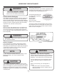
UNPACKING YOUR APPLIANCE ! Warranty Registration WARNING It is important you send in your warranty registration card immediately after taking delivery of your appliance or you can register online at www.agamarvel.com. EXCESSIVE WEIGHT HAZARD Use two or more people to move product. Failure to do so can result in personal injury. The following information will be required when registering your appliance.
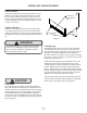
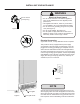
INSTALLING YOUR APPLIANCE Select Location The proper location will ensure peak performance of your appliance. We recommend a location where the unit will be out of direct sunlight and away from heat sources. To ensure your product performs to specifications, the recommended installation location temperature range is from 55 to 100°F (13 to 38°C). Front Grille, keep this area open. Cabinet Clearance Ventilation is required from the bottom front of the appliance.
INSTALLING YOUR APPLIANCE ! WARNING Electrical Shock Hazard Do not remove ground prong • Do not use an extension cord with this appliance. They can be hazardous and can degrade product performance. • This appliance should not, under any circumstances, be installed to an un-grounded electrical supply. • Do not remove the grounding prong from the power cord. (See Figure 3). • Do not use an adapter. (See Figure 4). • Do not splash or spray water from a hose on the appliance.
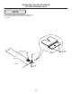
INSTALLING THE ANTI TIP DEVICE FOR FREESTANDING UNITS Anti-Tip Bracket WARNING ! • ALL APPLIANCES CAN TIP RESULTING IN INJURY. • INSTALL THE ANTI-TIP BRACKET PACKED WITH THE APPLIANCE. • FOLLOW THE INSTRUCTIONS BELOW 211⁄2" (54.
INSTALLING THE ANTI TIP DEVICE FOR FREESTANDING UNITS NOTE When the floor mounted anti-tip bracket is used the minimum adjusted height of the cabinet is increased by 3 ⁄8" (9 mm). nt o Fro net bi f ca line Sid eo f c Rear Leveling leg ab ine t li ne Figure 8a Screw 211⁄2" (54.
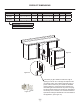
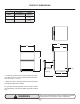
PRODUCT DIMENSIONS ROUGH-IN OPENING DIMENSIONS CABINET DIMENSIONS MODEL "A" "B" "C" "D" "E" "F" "G" "H" ML24RDS 24" (61 cm) **34" to 35" (86.4 cm to 88.9 cm) 24" (61 cm) 237⁄8" (60.7 cm) 333⁄4" to 343⁄4" (85.7 cm to 88.3 cm) 2323⁄32" (60.2 cm) 2521⁄32" (65.2 cm) 395⁄32" (99.5 cm) ML24RDP 24" (61 cm) **34" to 35" (86.4 cm to 88.9 cm) *24" (61 cm) 237⁄8" (60.7 cm) 333⁄4" to 343⁄4" (85.7 cm to 88.3 cm) 227⁄8" (58.1 cm) - 385⁄16" (97.
PRODUCT DIMENSIONS PRODUCT DATA MODEL ELECTRICAL REQUIREMENTS # PRODUCT WEIGHT ML24RDS 115V/60Hz/15A 130 lbs (59 kg) ML24RDP 115V/60Hz/15A 130 lbs (59 kg) "G" "D" "F" "E" 1" (2.5 cm) Figure 11 211⁄2" (54.6 cm) "H" * To install (P) models with the door face flush with adjacent cabinetry doors, custom decorative panel thickness cannot exceed 3⁄4" (19 mm). ** Minimum rough-in opening required is to be larger than the adjusted height of the cabinet.
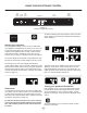
USING YOUR ELECTRONIC CONTROL Temp Minus keypad On/Off keypad Temp Plus keypad Lock keypad Display Area System Status indicators Figure 12 Electronic single zone control Power Failure ALARM RESET To wake the display press any keypad. A confirm tone will sound, and the current storage compartment temperature will be displayed. Starting your appliance: Plug the appliance power cord into a 115 volt wall outlet.
USING YOUR ELECTRONIC CONTROL Adjusting the temperature: Temperature mode: To set or check the set-point temperature (with the control out of sleep mode), press the "-" or "+" keypads. "SET" will be indicated on the user interface panel and the current set-point temperature will display and flash. Subsequent presses of the "-" or "+" keypads will adjust the temperature colder or warmer respectively.
USING YOUR ELECTRONIC CONTROL Alarms: The control will alert you to conditions that could adversely affect the performance of the appliance. Temp ALARM RESET Door Ajar • ALARM RESET • Door ajar - If a drawer is open, or not closed prop- erly, for more than 5-minutes the System Status OK indicator will turn-off, the "Door Ajar" indicator will flash, and a tone will sound every 60 seconds. Additionally, an "ALARM RESET" indicator will be displayed below the "On/Off" keypad.
USING YOUR ELECTRONIC CONTROL Vacation mode: This operating mode can be used to save energy during high cost energy periods, or when you won't be using your appliance for an extended period of time by disabling the lights, alarm tones, and keypad entry tones. Vacation mode also serves as a Sabbath mode, disabling functions and its controls in accordance with the weekly Sabbath and religious holidays observed within the Orthodox Jewish community.
OVERLAY DRAWER PANEL INSTALLATION ! CAUTION ! WARNING Electrocution Hazard It is important to use the factory provided grille that came with the product to assure proper air flow is maintained through the condenser. The use of a custom grille is not recommended and will void the warranty. • Never attempt to repair or perform maintenance on the appliance until the main electrical power has been disconnected. Turning the appliance control "OFF" does not remove electrical power from the units wiring.
OVERLAY DRAWER PANEL INSTALLATION Step 3: Attach the Overlay Panel to the Drawer .35/.31 (9 mm/7.5 mm) 1. Set the overlay panel on drawer front face and align edges. (See Figure 18). The custom overlay panel should be flush with the top of the drawer and centered on the width of the drawer. Clamp panel in position and mark pilot hole locations. Pick the required pilot hole size from "Table A" below and drill the pilot holes ensuring not to drill all the way through the overlay panel. Figure 16 .50 (12.
CARE AND CLEANING Drawer Divider The top drawer has an adjustable drawer divider. To adjust the divider, making the 4 areas larger or smaller, move the center post along the length of the rods in either direction. See Figure 19 and 19a. The divider can also be removed from the drawer. Front Grille Be sure that nothing obstructs the required air flow openings in front of the cabinet. At least once or twice a year, brush or vacuum lint and dirt from the front grille area (see page 4).
ENERGY SAVING TIPS AND OBTAINING SERVICE If Service is Required: The following suggestions will minimize the cost of operating your refrigeration appliance. 1. Do not install your appliance next to a hot appliance (cooker, dishwasher, etc.), heating air duct, or other heat sources. 2. Install product out of direct sunlight. 3. Ensure the front grille vents at front of appliance beneath drawer are not obstructed and kept clean to allow ventilation for the refrigeration system to expel heat. 4.
TROUBLESHOOTING Before You Call for Service If the appliance appears to be malfunctioning, read through this manual first. If the problem persists, check the troubleshooting guide below. Locate the problem in the guide and refer to the cause and its remedy before calling for service. The problem may be something very simple that can be solved without a service call. However, it may be required to contact your dealer or a qualified service technician.
HOUSEHOLD PRODUCT WARRANTY Entire Product Limited One Year Parts and Labor Warranty Parts or Service Not Supplied or Designated by AGA MARVEL AGA MARVEL warrants that it will supply all necessary parts and labor to repair or replace in the end user’s home or office, any component which proves to be defective in material or workmanship, subject to the condition and exclusions stated below, for a period of one year from the date of purchase by the end user.
www.agamarvel.com 1260 E. VanDeinse St. Greenville MI 48838 800.223.3900 41014808-EN Rev A 1/31/17 All specifications and product designs subject to change without notice. Such revisions do not entitle the buyer to corresponding changes, improvements, additions, replacements or compensation for previously purchased products.
EN Installation, Operation and Maintenance Instructions FR Instructions d’installation, d’utilisation et d’entretien ES Instrucciones de instalación, operación y mantenimiento Refrigerated Drawers Tiroirs réfrigérés Gavetas refrigeradas ML24RDS3** ML24RDP3**
CONTENU Contenu : Importantes instructions de sécurité Informations de sécurité.......................................................2 Déballage de votre appareil ..................................................3 Enregistrement de la garantie ......................................3 Installation de votre appareil ..............................................4 Dégagements par rapport à l’armoire .............................4 Mise à niveau de l’appareil .............................................
DÉBALLAGE DE VOTRE APPAREIL ! Enregistrement de la garantie AVERTISSEMENT Il est important que vous postiez votre carte de garantie immédiatement après avoir pris livraison de votre réfrigérateur. AVERTISSEMENT RISQUE DE POIDS EXCESSIF Les informations suivantes seront nécessaires au moment de l’enregistrement de votre appareil : Numéro de service Numéro de série Date d’achat Nom et adresse du revendeur Utilisez deux personnes ou plus pour déplacer le produit. Sinon vous pourriez vous blesser.
INSTALLATION DE VOTRE APPAREIL Choix de l’emplacement Un bon emplacement assurera une performance de pointe pour votre appareil. Nous recommandons un endroit où l’appareil ne sera pas exposé directement au rayonnement solaire et restera écarté de sources de chauffage. Pour assurer que les performances de votre produit soient au niveau de ses spécifications, la plage de températures recommandée au lieu d’installation sera de 55 à 100°F (13 à 38 °C). Grille frontale, gardez cette zone dégagée.
INSTALLATION DE VOTRE APPAREIL ! AVERTISSEMENT Risque de commotion électrique • N’utilisez pas de rallonge secteur avec cet appareil. Cela peut être dangereux et peut affecter la performance du produit. • Cet appareil ne doit sous aucun prétexte être installé sur une alimentation électrique sans liaison de terre. • N’enlevez pas la borne de terre de la fiche du cordon secteur. (Voyez la Figure 3). • N’utilisez pas d’adaptateur entre fiche et prise. (Voyez la Figure 4).
INSTALLATION DU DISPOSITIF ANTI-BASCULEMENT POUR DES INSTALLATIONS AUTONOMES ! Dispositif anti-basculement AVERTISSEMENT • TOUS LES APPAREILS PEUVENT BASCULER.
INSTALLATION DU DISPOSITIF ANTI-BASCULEMENT POUR DES INSTALLATIONS AUTONOMES REMARQUE Quand la ferrure anti-basculement fixée au sol est utilisée, la hauteur minimale ajustée de l’armoire est augmentée de 3 ⁄8 po (9 mm).
DIMENSIONS DU PRODUIT DIMENSIONS D’OUVERTURE BRUTE DIMENSIONS D’ARMOIRE MODÈLE «A» «B» «C» «D» «E» «F» «G» «H» ML24RDS 24 po (61 cm) **34 po à 35 po (86,4 cm à 88,9 cm) 24 po (61 cm) 237⁄8 po (60,7 cm) 333⁄4 po à 343⁄4 po (85,7 cm à 88,3 cm) 2323⁄32 po (60,2 cm) 2521⁄32 po (65,2 cm) 395⁄32 po (99,5 cm) ML24RDP 24 po (61 cm) **34 po à 35 po (86,4 cm à 88,9 cm) *24 po (61 cm) 237⁄8 po (60,7 cm) 333⁄4 po à 343⁄4 po (85,7 cm à 88,3 cm) 227⁄8 po (58,1 cm) - 385⁄16 po (97,3 cm) STYLE
DIMENSIONS DU PRODUIT DONNÉES DE PRODUIT MODÈLE BESOINS ÉLECTRIQUES # POIDS DU PRODUIT ML24RDS 115V/60Hz/15A 130 lb (59 kg) ML24RDP 115V/60Hz/15A 130 lb (59 kg) «G» «D» «F» «E» 1 po (2,5 cm) Figure 11 211⁄2 po (54,6 cm) «H» * Pour installer les modèles (F) avec la face de porte alignée avec les portes des meubles de rangement adjacents, l’épaisseur du panneau décoratif du client ne peut pas dépasser ¾ po (19mm).
UTILISATION DE VOTRE COMMANDE ÉLECTRONIQUE Diminution Augmentation Marche/ de de Arrêt température température Verrouillage des touches Zone d’affichage Indicateur de statut du système Figure 12 Commandes électroniques Power Failure Pour activer l’affichage, appuyez sur n’importe quelle touche. Un signal sonore de confirmation retentira, et la température actuelle du compartiment de conservation sera affichée.
UTILISATION DE VOTRE COMMANDE ÉLECTRONIQUE Réglage de la température : Mode d’affichage de température : Pour déterminer ou contrôler le point de consigne de température (avec la commande électronique sortie de son mode veille), appuyez sur les touches «-» ou «+». «SET» (Réglage) sera indiqué sur le panneau d’interface utilisateur et la consigne actuelle de température sera affichée et clignotera.
UTILISATION DE VOTRE COMMANDE ÉLECTRONIQUE Codes d’erreur des capteurs de température Les capteurs de température sont surveillés en permanence. Une condition de coupure (OPEN) ou de court-circuit (SHORTED) générera un CODE D’ERREUR tel que ceux qui suivent : Codes d’erreur des capteurs de température Capteur Code affiché Description de l’erreur Action à prendre Capteur de température de zone unique Panne de capteur de température dans le compartiment unique.
UTILISATION DE VOTRE COMMANDE ÉLECTRONIQUE Temp ALARM RESET • Panne de secteur - Si l’alimentation du réfrigérateur est interrompue l’indicateur de statut de système OK va s’éteindre, et l’indicateur de panne secteur (Power Failure) va clignoter. De plus un indicateur de restauration d’alerte (ALARM RESET) va être affiché sous la commande M/A (On/ Off). Il n’y aura pas de signalisation sonore. La condition d’alerte peut être supprimée momentanément en appuyant sur la commande M/A (On/Off).
INSTALLATION DE PANNEAU DE REVÊTEMENT DE TIROIR ! ATTENTION ! AVERTISSEMENT Risque d’électrocution Il est important d’utiliser la grille fournie par l’usine avec le produit pour assurer qu’un flux d’air approprié sera maintenu au travers du condenseur. L’utilisation d’une grille personnalisée n’est pas recommandée et annulerait la garantie. • Ne tentez jamais de réparer ou d’exécuter de la maintenance sur l’appareil avant que son alimentation électrique n’ait été débranchée en amont.
INSTALLATION DE PANNEAU DE REVÊTEMENT DE TIROIR 0,35/0,31 (9 mm/7,5 mm) Étape 3 : Fixez le panneau de revêtement sur le tiroir Figure 16 1. Placez le panneau de revêtement sur la face avant du tiroir et alignez les bords (Voyez la Figure 18 ci-dessous). Le panneau de revêtement personnalisé doit arriver au même niveau que le haut du tiroir, et le long de la largeur centrée du tiroir. Maintenez le panneau en position et marquez l’emplacement des avanttrous.
L’ENTRETIEN ET LE NETTOYAGE Séparateur de tiroir Le tiroir du haut a un séparateur de tiroir réglable. Pour régler le séparateur, faisant les 4 zones plus grandes ou plus petites, bougez le montant central le long de la longueur des tiges dans l’un ou l’autre sens. Voyez Figure 19 et 19a. Le séparateur peut aussi être enlevé du tiroir. Grille frontale Assurez-vous que rien n’obstrue les ouvertures pour flux d’air requises à l’avant de l’armoire.
CONSEILS POUR L’ÉCONOMIE D’ÉNERGIE, OBTENTION DE SERVICE Les suggestions suivantes vont minimiser le coût de fonctionnement de votre appareil de refroidissement. Si du service est nécessaire : N’installez pas votre appareil près d’un autre appareil chaud (cuisinière, lave-vaisselle, etc.), d’une conduite d’air chaud, ou d’autres sources de chaleur. 2. Placez l’appareil à l’abri du rayonnement solaire direct. 3.
DÉPANNAGE Avant d’appeler pour du service Si l’appareil semble présenter un dysfonctionnement, commencez par bien relire son manuel. Si le problème persiste, consultez le guide de dépannage qui suit. Identifiez le problème dans ce guide et consultez les colonnes de causes et de remèdes avant d’appeler pour du service. Le problème peut être quelque chose de très simple qui peut se résoudre sans demander une intervention de service.
GARANTIE DE PRODUIT À USAGE DOMESTIQUE Produit complet Garantie limitée d’un an sur pièces et main-d’œuvre Pièces ou service Non fourni ou désigné par AGA MARVEL Les garanties qui précèdent ne s’appliquent pas non plus si : AGA MARVEL garantit qu’il fournira toutes les pièces et la maind'œuvre nécessaires pour réparer ou remplacer, au domicile ou au bureau de l'utilisateur final, tout composant avéré défectueux du fait des matériaux ou de la main-d’œuvre, en tenant compte des conditions et exclusions déc
www.agamarvel.com 1260 E. VanDeinse St. Greenville MI 48838 800.223.3900 41014808-FR Rev A 2/24/17 Toutes les spécifications et les conceptions des produits sont sujet à des changements sans préavis. De telles révisions ne donnent aucun droit pour l’acheteur de produits antérieurs à bénéficier de ces changements, améliorations, ajouts, remplacements, ni de recevoir une compensation.
EN Installation, Operation and Maintenance Instructions FR Instructions d’installation, d’utilisation et d’entretien ES Instrucciones de instalación, operación y mantenimiento Refrigerated Drawers Tiroirs réfrigérés Gavetas refrigeradas ML24RDS3** ML24RDP3**
ÍNDICE Índice: Instrucciones importantes de seguridad Información de seguridad...............................................................2 Desembalaje de su artefacto..........................................................3 Registro de garantía..................................................................3 Instalación de su artefacto.............................................................4 Espacios libres alrededor del gabinete.....................................4 Nivelación del artefacto.
DESEMBALAJE DE SU ARTEFACTO ! Registro de garantía ADVERTENCIA Es importante que envíe su tarjeta de registro de la garantía inmediatamente después de haber recibido su artefacto; también puede registrarlo a través de Internet en la página www.agamarvel.com. RIESGO DE PESO EXCESIVO Se necesitan dos o más personas para mover el producto. Si no se procede así, pueden producirse lesiones personales.
INSTALACIÓN DE SU ARTEFACTO Selección de la ubicación La ubicación adecuada asegurará el desempeño óptimo de su artefacto. Recomendamos una ubicación en la que la unidad esté a cubierto de la luz solar directa y lejos de fuentes de calor. Para asegurar que su producto funcione de acuerdo con las especificaciones, el rango de temperaturas recomendado para la ubicación de instalación es de 55 a 100º F (de 13 a 38º C). Rejilla frontal: mantenga esta área abierta.
INSTALACIÓN DE SU ARTEFACTO ! ADVERTENCIA Peligro de choque eléctrico • No utilice cordones de extensión con este artefacto. Pueden ser peligrosos, y pueden degradar el funcionamiento del producto. • Este artefacto no debe conectarse en ninguna circunstancia a un suministro eléctrico sin conexión a tierra. • No quite la clavija de puesta a tierra del cordón de alimentación eléctrica. (vea la Figura 3). • No use un adaptador. (vea la Figura 4).
INSTALACIÓN DEL DISPOSITIVO ANTIVUELCO PARA INSTALACIONES AUTOSOSTENIDAS ! Soporte antivuelco ADVERTENCIA • TODOS LOS APARATOS SE PUEDEN VOLCAR. SE PUEDEN PRODUCIR LESIONES. • INSTALE EL SOPORTE ANTIVUELCO EMBALADO CON LA UNIDAD.
INSTALACIÓN DEL DISPOSITIVO ANTIVUELCO PARA INSTALACIONES AUTOSOSTENIDAS NOTA Cuando se utiliza el soporte antivuelco montado en el piso, la altura mínima ajustable del gabinete aumenta en 3⁄8" (9 mm).
DIMENSIONES DEL PRODUCTO DIMENSIONES DE LA ABERTURA DE INSTALACIÓN pulgadas (cm) DIMENSIONES DEL GABINETE pulgadas (cm) MODELO "A" "B" "C" "D" "E" "F" "G" "H" ML24RDS 24" (61 cm) **34" to 35" (86,4 cm to 88,9 cm) 24" (61 cm) 237⁄8" (60,7 cm) 333⁄4" to 343⁄4" (85,7 cm to 88,3 cm) 2323⁄32" (60,2 cm) 2521⁄32" (65,2 cm) 395⁄32" (99,5 cm) ML24RDP 24" (61 cm) **34" to 35" (86,4 cm to 88,9 cm) *24" (61 cm) 237⁄8" (60,7 cm) 333⁄4" to 343⁄4" (85,7 cm to 88,3 cm) 227⁄8" (58,1 cm) - 385⁄16
DIMENSIONES DEL PRODUCTO DATOS DEL PRODUCTO MODELO REQUISITOS ELÉCTRICOS # PESO DEL PRODUCTO ML24RDS 115V/60Hz/15A 130 lbs (59 kg) ML24RDP 115V/60Hz/15A 130 lbs (59 kg) "G" "D" "F" "E" 1" (2,5 cm) Figura 11 211⁄2" (54,6 cm) "H" * Para instalar modelos (P) con la cara de la puerta alineada con las puertas de los armarios adyacentes, el espesor del panel decorativo del cliente no puede exceder de ¾ de pulgada (19mm).
USO DE SU CONTROL ELECTRÓNICO Tecla Tecla para bajar “Encendido / la temperatura Apagado” Tecla para subir la temperatura Tecla “Bloqueo” Pantalla Indicadores de estado del sistema Figura 12 Control electrónico para una sola zona Power Failure ALARM RESET Para activar la pantalla, pulse cualquier tecla. Sonará un tono audible de confirmación y aparecerá la temperatura actual del compartimiento de almacenamiento.
USO DE SU CONTROL ELECTRÓNICO Ajuste de la temperatura: Modo de temperatura: Para establecer o ver el valor de consigna de la temperatura (con el control fuera del modo de espera), pulse la tecla “-” o “+”. La pantalla mostrará “SET” y el valor de consigna de la temperatura parpadeando. Para ajustar la temperatura más fría o más caliente, pulse repetidamente las teclas “-” o “+” respectivamente.
USO DE SU CONTROL ELECTRÓNICO Alarmas: El control emitirá un aviso cuando las condiciones podrían afectar negativamente al rendimiento del artefacto. NOTA La alarma de temperatura puede ocurrir como resultado de un uso intensivo o la introducción de los contenidos calientes en el compartimiento de almacenamiento. Si la alarma de temperatura persiste, su unidad puede requerir servicio.
USO DE SU CONTROL ELECTRÓNICO Modo Vacaciones: Este modo de operación se puede utilizar para ahorrar energía mediante la desactivación de las luces, los tonos de alarma y los tonos de entrada de teclado durante los períodos en los que el costo de la energía es elevado, o cuando el artefacto no será utilizado durante un tiempo prolongado.
INSTALACIÓN DEL PANEL DECORATIVO DE LA GAVETA ! PRECAUCION ADVERTENCIA ! Peligro de electrocución Es importante usar la rejilla provista de fábrica que viene con el producto para asegurar que se mantenga el flujo de aire a través del condensador. No se recomienda el uso de una rejilla personalizada pues anulará la garantía. • Nunca intente reparar o realizar tareas de mantenimiento en el artefacto sin haberlo previamente desconectado de la alimentación eléctrica.
INSTALACIÓN DEL PANEL DECORATIVO DE LA GAVETA Paso 3: fije el panel decorativo a la gaveta. 1. Coloque el panel decorativo en la cara delantera de la gaveta y alinee los bordes (vea la Figura 18 abajo). El panel decorativo 0,35/0,31 (9 mm/7,5 mm) Figura 16 cortado a la medida debe estar nivelado a tope con la parte superior de la gaveta y igualmente ambos lados de la gaveta. 0,50 (12,5) Sujete el panel en su posición y marque la ubicación de los agujeros de guía.
CUIDADOS Y LIMPIEZA Separador de gaveta La gaveta superior tiene un separador de gaveta ajustable. Para ajustar el separador, haciendo las 4 áreas más grandes o más pequeñas, mueva el poste central a lo largo de la longitud de las barras en cualquier dirección. Vea las Figuras 19 y 19a. El separador también se puede quitar de la gaveta. Rejilla frontal Verifique que nada obstruye el flujo de aire requerido en las aberturas delanteras del gabinete.
CONSEJOS PARA AHORRAR ENERGÍA, SOLICITUD DE SERVICIO TÉCNICO Las siguientes sugerencias reducirán al mínimo el costo de utilización de su artefacto de refrigeración. Si necesita asistencia técnica tenga en cuenta lo siguiente: 1. No instale el artefacto cerca de un electrodoméstico que emita calor (cocina, lavavajillas, etc.), conductos de calefacción y otras fuentes de calor. 2. Instale el producto alejado de la luz solar directa. 3.
LOCALIZACIÓN DE FALLAS Antes de llamar al servicio técnico siga estos consejos Si el artefacto parece estar funcionando mal, lea primero este manual. Si el problema persiste, vea la guía de localización de fallas incluida a continuación. Antes de llamar al servicio técnico, localice el problema en la guía y consulte su causa y su solución. Tal vez el problema sea algo muy simple que puede resolverse sin llamar al servicio técnico.
GARANTÍA DE PRODUCTOS ELECTRODOMÉSTICOS Para el producto completo Un año de garantía limitada sobre piezas y mano de obra del producto completo Piezas o servicios No provistos o designados por AGA MARVEL Las garantías indicadas tampoco serán de aplicación si: AGA MARVEL garantiza el suministro de todas las piezas y la mano de obra necesarias para reparar o reemplazar en el domicilio u oficina del usuario cualquier componente en el que se haya comprobado la presencia de defectos, sea por materiales o por m
www.agamarvel.com 1260 E. VanDeinse St. Greenville MI 48838 800.223.3900 41014808-SP Rev A 2/21/17 Todas las especificaciones y diseños del producto están sujetos a cambios sin aviso previo. Las revisiones del producto no le otorgan al comprador el derecho a cambios, mejoras, accesorios adicionales, reemplazos o compensaciones por los productos previamente comprados.