
Manual and User Guide


14
OVERLAY DRAWER PANEL INSTALLATION
Full Overlay Panel Installation Instructions
Determine Wood Screw Requirements
1. A #10 pan head wood screw should be used to proper-
ly secure the overlay panel (See Figure 16). A quantity
of 16 screws are supplied with the unit in the literature
pack.
2. Use only pan head screws.
3. If your overlay panel is thinner than
5
⁄8" (15.9 mm)
you will need to purchase shorter screws. The longer
screws will break through the front of the panel.
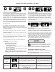
Figure 14
Remove screws
Clips
Gasket
Step 1: Remove Drawers from unit.
1. Begin by pulling out the top drawer. (See Figure 13).
Remove screws securing drawer to slides (See Figure
14). Pull drawer forward, lift up and out to clear clips in
rear of drawer. Move drawer forward about 1" (2.5 cm)
and set down on slides. At the right rear corner of the
drawer disconnect the display wire harness (See Figure
13a). Remove the drawer from the unit by lifting up off
of the slides. Repeat for bottom drawer but disregard
the harness instructions as there is no wiring to the bot-
tom drawer.
2. Remove the drawer divider from the top drawer and the
gasket from the drawer front. (See Figure 14). Do this
by pulling the gasket out of the channel that holds it to
the drawer front. This will expose the clearance holes
for mounting the overlay panel. (See Figure 18).
Figure 15
Figure 13
Press and hold down this
tab on the wire connec-
tor and pull the connector
apart.
Figure 13a
• Never attempt to repair or perform maintenance on
the appliance until the main electrical power has been
disconnected. Turning the appliance control "OFF"
does not remove electrical power from the units wiring.
• Replace all parts and panels before operating.
!
WARNING
Electrocution Hazard
!
CAUTION
It is important to use the factory provided grille that came
with the product to assure proper air ow is maintained
through the condenser. The use of a custom grille is not
recommended and will void the warranty.