EN Installation, Operation and Maintenance Instructions FR Instructions d’installation, d’utilisation et d’entretien ES Instrucciones de instalación, operación y mantenimiento Refrigerated Drawers Tiroirs réfrigérés Gavetas refrigeradas ML24RD
CONTENTS Important Safety Instructions Contents: Warnings and safety instructions appearing in this guide are not meant to cover all possible conditions and situations that may occur. Common sense, caution, and care must be exercised when installing, maintaining, or operating this appliance. Safety information ...............................................................2 Unpacking your appliance ..................................................3 Warranty registration .................................
UNPACKING YOUR APPLIANCE ! Warranty Registration WARNING It is important you send in your warranty registration card immediately after taking delivery of your appliance or you can register online at www.agamarvel.com. EXCESSIVE WEIGHT HAZARD Use two or more people to move product. Failure to do so can result in personal injury. The following information will be required when registering your appliance.
INSTALLING YOUR APPLIANCE Select Location The proper location will ensure peak performance of your appliance. We recommend a location where the unit will be out of direct sunlight and away from heat sources. To ensure your product performs to specifications, the recommended installation location temperature range is from 55 to 100°F (13 to 38°C). Front Grille, keep this area open. Cabinet Clearance Ventilation is required from the bottom front of the appliance.
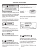
INSTALLING YOUR APPLIANCE ! WARNING Electrical Shock Hazard • Do not use an extension cord with this appliance. They can be hazardous and can degrade product performance. • This appliance should not, under any circumstances, be installed to an un-grounded electrical supply. • Do not remove the grounding prong from the power cord. • Do not use an adapter. • Do not splash or spray water from a hose on the appliance. Doing so may cause an electrical shock, which may result in severe injury or death.
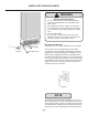
INSTALLING THE ANTI TIP DEVICE Anti-Tip Bracket WARNING ! • ALL APPLIANCES CAN TIP RESULTING IN INJURY. • INSTALL THE ANTI-TIP BRACKET PACKED WITH THE APPLIANCE. • FOLLOW THE INSTRUCTIONS BELOW 211⁄2" (54.6 cm) Leveling Leg Bottom View of Refrigerated Drawer Unit Front of cabinet Figure 5 Step by step instructions for locating the position of the bracket: Anti-Tip Device ! CAUTION 1) Decide where you want to place the drawer refrigerator.
INSTALLING THE ANTI TIP DEVICE ! WARNING TIP OVER HAZARD: One of the rear cabinet leveling legs must be engaged under an anti-tip bracket. nt o Fro net bi f ca line Sid eo f c Rear Leveling leg ab ine t li ne Figure 6a Screw 211⁄2" (54.
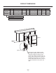
PRODUCT DIMENSIONS ROUGH-IN OPENING DIMENSIONS CABINET DIMENSIONS MODEL "A" "B" "C" "D" "E" "F" "G" "H" ML24RDS 24" (61 cm) **34" to 35" (86.4 cm to 88.9 cm) * 237⁄8" (60.7 cm) 333⁄4" to 343⁄4" (85.7 cm to 88.3 cm) 2323⁄32" (60.2 cm) 2521⁄32" (65.2 cm) 395⁄32" (99.5 cm) ML24RDP 24" (61 cm) **34" to 35" (86.4 cm to 88.9 cm) * 237⁄8" (60.7 cm) 333⁄4" to 343⁄4" (85.7 cm to 88.3 cm) 227⁄8" (58.1 cm) - 385⁄16" (97.
PRODUCT DIMENSIONS PRODUCT DATA MODEL ELECTRICAL REQUIREMENTS # PRODUCT WEIGHT ML24RDS 115V/60Hz/15A 130 lbs (59 kg) ML24RDP 115V/60Hz/15A 130 lbs (59 kg) "G" "D" "F" "E" 1" (2.5 cm) Figure 8 211⁄2" (54.6 cm) "H" * Depth dimension of rough-in opening may vary depending on each individual installation. To recess entire drawer "F" dimension plus 1" (2.5 cm) for thickness of power cord plug is required.
USING YOUR ELECTRONIC CONTROL Temp Minus keypad On/Off keypad Temp Plus keypad Lock keypad Display Area System Status indicators Figure 9 Electronic single zone control Power Failure ALARM RESET To wake the display press any keypad. A confirm tone will sound, and the current storage compartment temperature will be displayed. Starting your appliance: Plug the appliance power cord into a 115 volt wall outlet.
USING YOUR ELECTRONIC CONTROL Adjusting the temperature: To set or check the set-point temperature (with the control out of sleep mode), press the "-" or "+" keypads. "SET" will be indicated on the user interface panel and the current set-point temperature will display and flash. Subsequent presses of the "-" or "+" keypads will adjust the temperature colder or warmer respectively.
USING YOUR ELECTRONIC CONTROL Vacation mode: Power Failure • Power failure - If power to the appliance is inter- rupted the System Status indicator will turn-off and the "Power Failure" indicator will flash. Additionally, an "ALARM RESET" indicator will be displayed below the "On/Off" keypad. No audible tone will sound. This alarm condition can be reset by momentarily pressing the "On/Off" keypad.
OVERLAY DRAWER PANEL INSTALLATION ! CAUTION ! WARNING Electrocution Hazard It is important to use the factory provided grille that came with the product to assure proper air flow is maintained through the condenser. The use of a custom grille is not recommended and will void the warranty. • Never attempt to repair or perform maintenance on the appliance until the main electrical power has been disconnected. Turning the appliance control "OFF" does not remove electrical power from the units wiring.
OVERLAY DRAWER PANEL INSTALLATION Step 3: Attach the Overlay Panel to the Drawer 1. Set the overlay panel on drawer front face and align edges. (See Figure 15 below). The custom overlay panel should be flush with the top of the drawer and centered on the width of the drawer. Clamp panel in position and mark pilot hole locations. Pick the required pilot hole size from "Table B" below and drill the pilot holes ensuring not to drill all the way through the overlay panel. .35/.31 (9 mm/7.5 mm) Figure 13 .
OVERLAY DRAWER PANEL INSTALLATION Step 4: Reinstall the Drawers 1. Fully extend drawer slides and place drawer on slides. Be sure that drawer sits evenly on both slides and clips slide into place in rear of drawer. 2. Re-install wire harness at rear corner of top drawer. 3. Re-install two screws through drawer into slides. Screw clearance hole through gasket extrusion Figure 15a Overlay panel flush with top edge of drawer Custom overlay panel to be centered on width of drawer.
CARE AND CLEANING AND ENERGY SAVING TIPS Front Grille Be sure that nothing obstructs the required air flow openings in front of the cabinet. At least once or twice a year, brush or vacuum lint and dirt from the front grille area (see page 4). ! CAUTION SHOCK HAZARD: Disconnect electrical power from the appliance before cleaning with soap and water. Cabinet The painted cabinet can be washed with either a mild soap and water and thoroughly rinsed with clear water. NEVER use abrasive scouring cleaners.
OBTAINING SERVICE If Service is Required: • If the product is within the first year warranty period please contact your dealer or call AGA MARVEL Customer Service at 800.223.3900 for directions on how to obtain warranty coverage in your area. • If the product is outside the first year warranty period, AGA MARVEL Customer Service can provide recommendations of service centers in your area. A listing of authorized service centers is also available at www. agamarvel.
TROUBLESHOOTING Before You Call for Service If the appliance appears to be malfunctioning, read through this manual first. If the problem persists, check the troubleshooting guide below. Locate the problem in the guide and refer to the cause and its remedy before calling for service. The problem may be something very simple that can be solved without a service call. However, it may be required to contact your dealer or a qualified service technician.
HOUSEHOLD PRODUCT WARRANTY Entire Product Limited One Year Parts and Labor Warranty Parts or Service Not Supplied or Designated by AGA MARVEL AGA MARVEL warrants that it will supply all necessary parts and labor to repair or replace in the end user’s home or office, any component which proves to be defective in material or workmanship, subject to the condition and exclusions stated below, for a period of one year from the date of purchase by the end user.
www.agamarvel.com 1260 E. VanDeinse St. Greenville MI 48838 800.223.3900 41013359-EN Rev D 11/5/14 All specifications and product designs subject to change without notice. Such revisions do not entitle the buyer to corresponding changes, improvements, additions, replacements or compensation for previously purchased products.