EN Installation, Operation and Maintenance Instructions FR Instructions d’installation, d’utilisation et d’entretien ES Instrucciones de instalación, operación y mantenimiento Built in Refrigerators Réfrigérateurs intégrées Refrigeradores empotradas MP15BCG4** MP15BCF4** MP24BCG4** MP24BCF4** MP24BRG4** MP24BRF4** MP24RAS4** MP24RAP4** MP24WBG4** MP24WBF4**
CONTENTS Important Safety Instructions Contents: Warnings and safety instructions appearing in this guide are not meant to cover all possible conditions and situations that may occur. Common sense, caution, and care must be exercised when installing, maintaining, or operating this appliance. Safety information ...............................................................2 Unpacking your appliance ..................................................3 Warranty registration .................................
UNPACKING YOUR APPLIANCE ! Warranty Registration WARNING It is important you send in your warranty registration card immediately after taking delivery of your appliance or you can register online at www.agamarvel.com. EXCESSIVE WEIGHT HAZARD Use two or more people to move product. Failure to do so can result in personal injury. The following information will be required when registering your appliance.
INSTALLING YOUR APPLIANCE Select Location The proper location will ensure peak performance of your appliance. We recommend a location where the unit will be out of direct sunlight and away from heat sources. To ensure your product performs to specifications, the recommended installation location temperature range is from 55 to 100°F (13 to 38°C). Front Grille, keep this area open. Cabinet Clearance Ventilation is required from the bottom front of the appliance.
INSTALLING YOUR APPLIANCE ! WARNING Electrical Shock Hazard Do not remove ground prong • Do not use an extension cord with this appliance. They can be hazardous and can degrade product performance. • This appliance should not, under any circumstances, be installed to an un-grounded electrical supply. • Do not remove the grounding prong from the power cord. (See Figure 3). • Do not use an adapter. (See Figure 4). • Do not splash or spray water from a hose on the appliance.
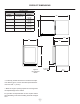
PRODUCT DIMENSIONS ROUGH-IN OPENING DIMENSIONS MODEL "A" "B" MP15BCG 15" (38.1 cm) MP15BCF CABINET DIMENSIONS "C" "D" "E" "F" "G" "H" "J" **34 ⁄4" to 35 ⁄4" (87 to 89.5 cm) 24" (61 cm) 7 14 ⁄8" (37.8 cm) 34" to 35" (86.4 to 88.9 cm) 23 ⁄32" (60.2 cm) 26 ⁄32" (66.6 cm) 13 37 ⁄32" (95 cm) 177⁄16" (44.3 cm) 15" (38.1 cm) **341⁄4" to 351⁄4" (87 to 89.5 cm) * 24" (61 cm) 147⁄8" (37.8 cm) 34" to 35" (86.4 to 88.9 cm) 227⁄8" (58.1 cm) - 71⁄2" (95.2 cm) 141⁄8" (35.
PRODUCT DIMENSIONS PRODUCT DATA MODEL ELECTRICAL REQUIREMENTS # PRODUCT WEIGHT MP15BCG 115V/60Hz/15A 105 lbs (47.6 kg) MP15BCF 115V/60Hz/15A 105 lbs (47.6 kg) MP24**S 115V/60Hz/15A 140 lbs (63.6 kg) MP24**G 115V/60Hz/15A 140 lbs (63.6 kg) MP24**F 115V/60Hz/15A 140 lbs (63.6 kg) "H" "J" "G" "D" "F" "E" Figure 9 (S) solid door shown * To install (F) models with the door face flush with adjacent cabinetry doors, custom decorative panel thickness cannot exceed 3⁄4" (19 mm).
USING YOUR ELECTRONIC CONTROL Temp Minus keypad On/Off keypad Upper/Lower Temp zones Plus (Dual Zone keypad models only) Display Area Lights keypad Lock keypad System Status indicators Figure 10 Electronic control Power Failure ALARM RESET Starting your appliance (single and dual zone): Plug the appliance power cord into a 115 volt wall outlet. Your appliance is shipped from the factory in the "On" position and will begin start-up of cooling as soon as power is supplied.
USING YOUR ELECTRONIC CONTROL Interior Lighting: Factors that affect the storage compartment stabilized temperature: • Changes to temperature setting. • Room temperature changes. • Temperature of stored contents. - Loading warm contents. - Cold content load will delay the change to a warmer set-point temperature. - Warm content load will delay the change to a colder set-point temperature. • Usage, (number and duration of the door openings).
USING YOUR ELECTRONIC CONTROL To change the set temperature for a particular zone, with the zone selected and out of sleep mode, press the "-" or "+" keypads. "SET" will be indicated on the user interface panel and the current set-point temperature will display and flash. Subsequent presses of the "-" or "+" keypads will adjust the temperature colder or warmer respectively.
USING YOUR ELECTRONIC CONTROL NOTE Temp If the control lock is active (illuminated lock icon) the control will have to be unlocked before using the keypad to reset an alarm condition. See page 10 (Control Lock) for instructions for unlocking the control. ALARM RESET • Alarms (single and dual zone): The control will alert you to conditions that could adversely affect the performance of the appliance.
OVERLAY DOOR PANEL INSTALLATION Vacation mode (single and dual zone): This operating mode can be used to save energy during high cost energy periods, or when you won't be using your appliance for an extended period of time by disabling the lights, alarm tones, and keypad entry tones. Vacation mode also serves as a Sabbath mode, disabling functions and its controls in accordance with the weekly Sabbath and religious holidays observed within the Orthodox Jewish community.
OVERLAY DOOR PANEL INSTALLATION ! WARNING Press and hold this down this tab on the wire connector and pull the connector apart. Use extreme caution with the articulated hinges. The hinge is self closing and many pinch points exist prior to built-in installation. Do not remove the cabinet "Z" bracket from the top of the cabinet.
OVERLAY DOOR PANEL INSTALLATION ! CAUTION Clearance for hinge 2 places Hinge side of door Weight of overlay door panel must not exceed 15 pounds (6.8 kg) for a solid door model or 10 pounds (4.5 kg) for a glass door model. Figure 16 Right Hand Hinged Door 15" (38.1 cm) wide appliance Figure 14 Left Hand Hinged Door 15" (38.1 cm) wide appliance Clearance for hinge 2 places 143⁄4" (37.5 cm) 1 ⁄4" (6 mm) Deep 1 143⁄4" (37.5 cm) ⁄4" (6 mm) Deep 1" (25.4 mm) diameter counter bore 1⁄4" (6.
OVERLAY DOOR PANEL INSTALLATION Clearance for screw head, 4 places or Hinge side of door 233⁄4" (60.3 cm) ⁄4" (6 mm) Deep 1 13⁄16" (3 cm) Clearance for screw head, 4 places do or 233⁄4" (60.3 cm) 1 ⁄4" (6 mm) Deep 13⁄4" (4.4 cm) 13⁄4" (4.4 cm) 14" (35.6 cm) of Figure 20 Right Hand Hinged Door 24" (61 cm) wide appliance Figure 18 Left Hand Hinged Door 24" (61 cm) wide appliance 47⁄8" (12.
OVERLAY DOOR PANEL INSTALLATION ! CAUTION Weight of overlay door panel must not exceed 15 pounds (6.8 kg) for a solid door model or 10 pounds (4.5 kg) for a glass door model. Counter bore lock hole on back side. #10 x 1⁄2" screw Figure 22a Material Type #10 Wood Screw Hardwood 1 Softwood 7 ⁄8" (3.2 mm) Diameter. Pilot Hole ⁄64 (2.8 mm) Diameter. Pilot Hole ⁄32" (13.
OVERLAY DOOR PANEL INSTALLATION Step 5: Assemble lock parts Step 7: Install the door Two (2) lock extensions are provided with the lock. Use the longer extension for 3⁄4" thick overlay panels and the shorter one for 5⁄8" thick overlay panels. Assemble the lock extension, cam stop washer, spring washer, and set screw to the lock as shown in Figure 23 and 24. Carefully open the top and bottom hinges on the door being careful as there are many pinch points.
SHELVING CONFIGURATIONS Loading Tips and Suggestions Your appliance is equipped with a cantilever shelf system which provides maximum adjust ability and customizing of the shelving arrangements listed below. Figure 28 Refrigerator: 24" (61 cm) Wide Models: Shown with a solid door with door racks. Figure 28. Figure 26 (1) half width metal cantilever shelf (See Figure 36). (1) full width slide out cantilever metal shelf. (See Figure 35). (1) frame and flat glass crisper cover. (1) roll-out crisper pan.
SHELVING CONFIGURATIONS Figure 36 half width metal cantilever shelf Figure 31 glide out wine convertible glass shelf Wine shelf underneath glass Figure 37 Figure 32 Wine cutout and flat glass shelf with vibration dampening mat, the glass can be removed for wine storage.
SHELVING CONFIGURATIONS Tall bottle storage area Installed shelf tang Shelf support slot Rear tang (hook) on shelf Figure 41 Door storage racks To remove the crisper : Pull out until it stops. Lift up on the front of the pan, and remove it from the frame. Figure 40a To Add or Remove a Shelf Remove stored product from the shelf. Do not try to remove a loaded shelf from the appliance. Grasp the shelf front with both hands, rotate the front upward and lift out. (See Figure 40b).
CARE AND CLEANING AND ENERGY SAVING TIPS Front Grille Be sure that nothing obstructs the required air flow openings in front of the cabinet. At least once or twice a year, brush or vacuum lint and dirt from the front grille area (see page 4). ! CAUTION SHOCK HAZARD: Disconnect electrical power from the appliance before cleaning with soap and water. Cabinet The painted cabinet can be washed with either a mild soap and water and thoroughly rinsed with clear water. NEVER use abrasive scouring cleaners.
OBTAINING SERVICE If Service is Required: • If the product is within the first year warranty period please contact your dealer or call AGA MARVEL Customer Service at 800.223.3900 for directions on how to obtain warranty coverage in your area. • If the product is outside the first year warranty period, AGA MARVEL Customer Service can provide recommendations of service centers in your area. A listing of authorized service centers is also available at www. agamarvel.
TROUBLESHOOTING Before You Call for Service If the appliance appears to be malfunctioning, read through this manual first. If the problem persists, check the troubleshooting guide below. Locate the problem in the guide and refer to the cause and its remedy before calling for service. The problem may be something very simple that can be solved without a service call. However, it may be required to contact your dealer or a qualified service technician.
HOUSEHOLD PRODUCT WARRANTY Entire Product Limited One Year Parts and Labor Warranty Parts or Service Not Supplied or Designated by AGA MARVEL AGA MARVEL warrants that it will supply all necessary parts and labor to repair or replace in the end user’s home or office, any component which proves to be defective in material or workmanship, subject to the condition and exclusions stated below, for a period of one year from the date of purchase by the end user.
www.agamarvel.com 1260 E. VanDeinse St. Greenville MI 48838 800.223.3900 41014796-EN Rev B 4/6/17 All specifications and product designs subject to change without notice. Such revisions do not entitle the buyer to corresponding changes, improvements, additions, replacements or compensation for previously purchased products.
EN Installation, Operation and Maintenance Instructions FR Instructions d’installation, d’utilisation et d’entretien ES Instrucciones de instalación, operación y mantenimiento Built in Refrigerators Réfrigérateurs intégrées Refrigeradores empotradas MP15BCG4** MP15BCF4** MP24BCG4** MP24BCF4** MP24BRG4** MP24BRF4** MP24RAS4** MP24RAP4** MP24WBG4** MP24WBF4**
CONTENU Importantes instructions de sécurité Contenu : Les avertissements et les instructions de sécurité qui apparaissent dans ce guide n’ont pas la prétention de couvrir toutes les conditions et situations possibles pouvant arriver. Il faut faire preuve de bon sens, de précautions et de soins, pour installer, utiliser ou entretenir cet appareil. Informations de sécurité.......................................................2 Déballage de votre appareil ..................................................
DÉBALLAGE DE VOTRE APPAREIL Enregistrement de la garantie AVERTISSEMENT ! Il est important que vous postiez votre carte de garantie immédiatement après avoir pris livraison de votre réfrigérateur. AVERTISSEMENT RISQUE DE POIDS EXCESSIF Les informations suivEnregistrment en ligne antes seront nécesdisponible sur saires au moment de www.agamarvel.
INSTALLATION DE VOTRE APPAREIL Choix de l’emplacement Un bon emplacement assurera une performance de pointe pour votre appareil. Nous recommandons un endroit où l’appareil ne sera pas exposé directement au rayonnement solaire et restera écarté de sources de chauffage. Pour assurer que les performances de votre produit soient au niveau de ses spécifications, la plage de températures recommandée au lieu d’installation sera de 55 à 100°F (13 à 38 °C). Grille frontale, gardez cette zone dégagée.
INSTALLATION DE VOTRE APPAREIL ! AVERTISSEMENT Risque de commotion électrique • N’utilisez pas de rallonge secteur avec cet appareil. Cela peut être dangereux et peut affecter la performance du produit. • Cet appareil ne doit sous aucun prétexte être installé sur une alimentation électrique sans liaison de terre. • N’enlevez pas la borne de terre de la fiche du cordon secteur. (Voyez la Figure 3). • N’utilisez pas d’adaptateur entre fiche et prise. (Voyez la Figure 4).
DIMENSIONS DU PRODUIT DIMENSIONS D’OUVERTURE BRUTE DIMENSIONS D’ARMOIRE MODÈLE «A» «B» «C» «D» «E» «F» «G» «H» «J» MP15BCG 15 po (38.1 cm) **341⁄4 po à 351⁄4 po (87 à 89,5 cm) 24 po (61 cm) 147⁄8 po (37.8 cm) 34 po à 35 po (86.4 à 88.9 cm) 2323⁄32 po (60.2 cm) 267⁄32 po (66.6 cm) 3713⁄32 po (95 cm) 177⁄16 po (44.3 cm) MP15BCF 15 po (38.1 cm) **341⁄4 po à 351⁄4 po (87 à 89,5 cm) * 24 po (61 cm) 147⁄8 po (37.8 cm) 34 po à 35 po (86.4 à 88.9 cm) 227⁄8 po (58.1 cm) - 71⁄2 po (95.
DIMENSIONS DU PRODUIT DONNÉES DE PRODUIT MODÈLE BESOINS ÉLECTRIQUES # POIDS DU PRODUIT MP15BCG 115V/60Hz/15A 105 lb (47.6 kg) MP15BCF 115V/60Hz/15A 105 lb (47.6 kg) MP24**S 115V/60Hz/15A 140 lb (63.6 kg) MP24**G 115V/60Hz/15A 140 lb (63.6 kg) MP24**F 115V/60Hz/15A 140 lb (63.6 kg) «H» «J» «G» «D» «F» «E» 31⁄2 po (8.
UTILISATION DE VOTRE COMMANDE ÉLECTRONIQUE Augmentation de température Diminution de température Zones supérieure/ inférieure (Modèles à deux zones uniquement) Marche/ Arrêt Power Failure Zone d’affichage Allumage d’éclairage Verrouillage des touches Indicateur de statut du système Figure 10 Commandes électroniques ALARM RESET Démarrage de votre réfrigérateur : Branchez la prise du cordon d’alimentation du réfrigérateur dans une prise murale de secteur 115 V.
UTILISATION DE VOTRE COMMANDE ÉLECTRONIQUE commande M/A (On/Off) pour valider, ou si vous ne faites rien le mode de réglage va se désactiver 10 secondes après, et la température affichée sera prise comme le prochain point de consigne. Changement d’éclairage tricolore: Pour changer le couleur entre le blanc, l’ambre et le bleu, avec la commande électronique sortie du mode veille, appuyez sur la commande d’éclairage (symbole d’ampoule). L’icône d’ampoule d’éclairage va s’allumer.
UTILISATION DE VOTRE COMMANDE ÉLECTRONIQUE Verrouillage des commandes : Mode d’affichage de température : Le mode de température est préréglé en usine pour degrés Fahrenheit (°F), mais vous avez l’option de commuter l’affichage en degrés Celsius (°C). Pour changer de mode d’affichage, actionnez et maintenez appuyée la commande «-» tout en appuyant sur la commande «+», puis relâchez seulement la commande «-». L’affichage de température se fera maintenant en degrés Celsius (°C).
UTILISATION DE VOTRE COMMANDE ÉLECTRONIQUE Alertes : La commande va vous alerter en cas de conditions pouvant nuire à la performance de l’appareil. Temp • Door Ajar ALARM RESET • Porte entrouverte - Si la porte reste ouverte ou incorrectement fermée, pendant plus de 5 minutes, l’indicateur de statut de système OK va s’éteindre, l’indicateur de porte entrouverte (Door Ajar) va clignoter et une tonalité va retentir toutes les 60 secondes.
UTILISATION DE VOTRE COMMANDE ÉLECTRONIQUE Mode de vacances : Ce mode de fonctionnement peut être utilisé pour économiser de l’énergie durant les périodes où elle est la plus coûteuse, ou si vous n’utilisez pas votre appareil pendant une période prolongée, en désactivant ses éclairages, tonalités d’alerte, et sonorités d’actionnement des commandes.
INSTALLATION DE PANNEAU DE REVÊTEMENT DE PORTE Si vous avez acheté un modèle à panneau de revêtement, votre réfrigérateur est équipé de charnières articulées pour permettre des installations complètement encastrées. Des épaisseurs de panneau de 5⁄8 po (15 mm) et 3⁄4 po (18 mm) sont acceptées. Desserrez (n’enlevez pas) ces deux vis à tête Phillip des charnières du haut et du bas.
INSTALLATION DE PANNEAU DE REVÊTEMENT DE PORTE ! AVERTISSEMENT Utilisez une extrême prudence avec les charnières articulées. La charnière se referme toute seule et il existe de nombreux points de pinçage avant l’installation encastrée. N’enlevez pas la cornière en «Z» du haut de l’armoire. Étape 2 : Dépose du joint de porte Avec la porte reposant sur une surface plane, et en partant d’un des ses angles, ôtez le joint de porte magnétique de la face intérieure de la porte (Voyez la Figure 13).
INSTALLATION DE PANNEAU DE REVÊTEMENT DE PORTE Dégagement pour tête de vis, 4 Ha emplacements ut d ort e Côté charnières de la porte Le poids du revêtement de porte ne doit pas dépasser 15 lb (6,8 kg) pour un modèle à porte pleine, ou 10 lb (4,5 kg) pour un modèle à porte vitrée.
INSTALLATION DE PANNEAU DE REVÊTEMENT DE PORTE Côté charnières de la porte Ha e ort ep d ut Dégagement pour charnière, 2 emplacements Dégagement pour charnière, 2 emplacements Ha ut 233⁄4 po (60,7 cm) 13⁄4 po (4,4 cm) 13⁄4 po (4,4 cm) 13⁄16 po (3 cm) rte 233⁄4 po (60,3 cm) 1 ⁄4 po (6 mm) Profondeur 1 ⁄4 po (6 mm) Profondeur 14 po (35,6 cm) po Dégagement pour tête de vis, 4 emplacements Figure 20 Porte à charnières à droite Appareil de largeur 24 po (61 cm) Figure 18 Porte à charnières à
INSTALLATION DE PANNEAU DE REVÊTEMENT DE PORTE ! ATTENTION Le poids du revêtement de porte ne doit pas dépasser 15 lb (6,8 kg) pour un modèle à porte pleine, ou 10 lb (4,5 kg) pour un modèle à porte vitrée. Trou de verrou alésé sur la face arrière Vis #10 x 1 ⁄2 po Figure 22a Type de matériau Vis à bois #10 Bois dur Avant trou Ø 1⁄8 po (2 mm) Bois tendre Avant trou Ø 7⁄64 (0,8 mm) Tableau B ⁄32" (13.
INSTALLATION DE PANNEAU DE REVÊTEMENT DE PORTE Étape 5 : Montez les pièces de verrou Deux (2) extensions de verrouillage sont fournies avec le verrou. Utilisez l’extension la plus longue pour un panneau de revêtement d’épaisseur 3⁄4 po et la plus courte pour un panneau d’épaisseur 5⁄8 po. Assemblez l’extension de verrouillage, une rondelle d’arrêt de came, une rondelle élastique et une vis de fixation sur le verrou comme montré aux Figures 23 et 24.
INSTALLATION DE PANNEAU DE REVÊTEMENT DE PORTE Étape 7 : Installez la porte Ouvrez soigneusement les charnières du haut et du bas sur la porte en vous méfiant des nombreux points de pinçage. Placez les charnières par-dessus les 4 vis dans l’armoire, 2 en haut et 2 en bas, et glissez la porte en position. Serrez ces 4 vis de charnières avec un tournevis à pointe Phillips (Voyez les Figures 11 et 11a).
CONFIGURATIONS DE ÉTAGÈRES Conseils et suggestions pour le chargement Votre réfrigérateur est équipé d’un système de étagères en porteà-faux qui procure une capacité maximale d’ajustement et une personnalisation des arrangements comme c’est montré plus loin. Réfrigérateur : Appareils de largeur 24 po (61 cm) : Montré avec une porte pleine équipée de balconnets en Figure 28. (1) Faites glisser étagère en porte à faux de métal (Voyez la Figure 35).
CONFIGURATIONS DE ÉTAGÈRES Deux zones: du vin / stockage de boissons : Appareils de largeur 24 po (61 cm) : Montré avec une porte vitrée en Figure 30. Zone supérieure : (1) étagère-présentoir pour 7 bouteilles avec tapis atténuateur de vibrations (Voyez la figure 37). Zone inférieure : (1) étagère en porte-à faux, encadrement et verre 4 bouteilles (Voyez la figure 39). (1) étagère en porte-à faux, encadrement et verre déploiement (Voyez la figure 38).
CONFIGURATIONS DE ÉTAGÈRES Zone de stockage de grandes bouteilles Figure 36 Balconnets de stockage de porte Figure 40 Figure 37 Pour ôter le bac à légumes : Tirez-le jusqu’à ce qu’il s’arrête. Levez l’avant du bac, et dégagez-le du logement.
CONFIGURATIONS DE ÉTAGÈRES ! Pour ajouter ou enlever une étagère ATTENTION Assurez-vous que votre étagère en porte-à-faux est bien en place sur les supports en appuyant dessus avant de la charger. Fente de support de étagère Enlevez les produits qui étaient entreposés sur la étagère. N’essayez pas d’enlever une étagère du réfrigérateur restée chargée. Prenez le devant de la étagère des deux mains, faites pivoter son avant vers le haut et enlevez-la (Voyez la Figure 41b).
CONSEILS POUR L’ÉCONOMIE D’ÉNERGIE, L’ENTRETIEN ET LE NETTOYAGE Grille frontale Assurez-vous que rien n’obstrue les ouvertures pour flux d’air requises à l’avant de l’armoire. Au moins une à deux fois par an, chassez par brossage ou par aspiration les peluches et les saletés dans la zone de la grille avant (Voyez en page 4). ! ATTENTION Les suggestions suivantes vont minimiser le coût de fonctionnement de votre appareil de refroidissement. 1. 2. 3.
OBTENTION DE SERVICE Si du service est nécessaire : • Si le produit est encore dans sa première année de garantie, veuillez appeler le service à la clientèle d’AGA MARVEL au 800.223.3900 pour avoir des instructions sur la façon d’obtenir une couverture sous garantie dans votre secteur. • Si le produit est sorti de sa première année de garantie, le service à la clientèle d’AGA MARVEL peut vous fournir des recommandations sur les centres de service de votre secteur.
DÉPANNAGE Avant d’appeler pour du service Si l’appareil semble présenter un dysfonctionnement, commencez par bien relire son manuel. Si le problème persiste, consultez le guide de dépannage qui suit. Identifiez le problème dans ce guide et consultez les colonnes de causes et de remèdes avant d’appeler pour du service. Le problème peut être quelque chose de très simple qui peut se résoudre sans demander une intervention de service.
GARANTIE DE PRODUIT À USAGE DOMESTIQUE Produit complet Garantie limitée d’un an sur pièces et main-d’œuvre Pièces ou service Non fourni ou désigné par AGA MARVEL Les garanties qui précèdent ne s’appliquent pas non plus si : AGA MARVEL garantit qu’il fournira toutes les pièces et la maind'œuvre nécessaires pour réparer ou remplacer, au domicile ou au bureau de l'utilisateur final, tout composant avéré défectueux du fait des matériaux ou de la main-d’œuvre, en tenant compte des conditions et exclusions déc
www.agamarvel.com 1260 E. VanDeinse St. Greenville MI 48838 800.223.3900 41014796-FR Rev B 4/6/17 Toutes les spécifications et les conceptions des produits sont sujet à des changements sans préavis. De telles révisions ne donnent aucun droit pour l’acheteur de produits antérieurs à bénéficier de ces changements, améliorations, ajouts, remplacements, ni de recevoir une compensation.
EN Installation, Operation and Maintenance Instructions FR Instructions d’installation, d’utilisation et d’entretien ES Instrucciones de instalación, operación y mantenimiento Built in Refrigerators Réfrigérateurs intégrées Refrigeradores empotradas MP15BCG4** MP15BCF4** MP24BCG4** MP24BCF4** MP24BRG4** MP24BRF4** MP24RAS4** MP24RAP4** MP24WBG4** MP24WBF4**
ÍNDICE Índice: Instrucciones importantes de seguridad Información de seguridad...............................................................2 Desembalaje de su artefacto..........................................................3 Registro de garantía..................................................................3 Instalación de su artefacto.............................................................4 Espacios libres alrededor del gabinete.....................................4 Nivelación del artefacto.
DESEMBALAJE DE SU ARTEFACTO ! Registro de garantía ADVERTENCIA Es importante que envíe su tarjeta de registro de la garantía inmediatamente después de haber recibido su artefacto; también puede registrarlo a través de Internet en la página www.agamarvel.com. RIESGO DE PESO EXCESIVO Se necesitan dos o más personas para mover el producto. Si no se procede así, pueden producirse lesiones personales.
INSTALACIÓN DE SU ARTEFACTO Selección de la ubicación La ubicación adecuada asegurará el desempeño óptimo de su artefacto. Recomendamos una ubicación en la que la unidad esté a cubierto de la luz solar directa y lejos de fuentes de calor. Para asegurar que su producto funcione de acuerdo con las especificaciones, el rango de temperaturas recomendado para la ubicación de instalación es de 55 a 100º F (de 13 a 38º C). Rejilla frontal: mantenga esta área abierta.
INSTALACIÓN DE SU ARTEFACTO ! ADVERTENCIA Peligro de choque eléctrico • No utilice cordones de extensión con este artefacto. Pueden ser peligrosos, y pueden degradar el funcionamiento del producto. • Este artefacto no debe conectarse en ninguna circunstancia a un suministro eléctrico sin conexión a tierra. • No quite la clavija de puesta a tierra del cordón de alimentación eléctrica. (vea la Figura 3). • No use un adaptador. (vea la Figura 4).
DIMENSIONES DEL PRODUCTO DIMENSIONES DE LA ABERTURA DE INSTALACIÓN pulgadas (cm) DIMENSIONES DEL GABINETE pulgadas (cm) MODELO "A" "B" "C" "D" "E" "F" "G" "H" "J" MP15BCG 15" (38,1 cm) **341⁄4" a 351⁄4" (87 a 89,5 cm) 24" (61 cm) 147⁄8" (37,8 cm) 34" a 35" (86,4 a 88,9 cm) 2323⁄32" (60,2 cm) 267⁄32" (66,6 cm) 3713⁄32" (95 cm) 177⁄16" (44,3 cm) MP15BCF 15" (38,1 cm) **341⁄4" a 351⁄4" (87 a 89,5 cm) * 24" (61 cm) 147⁄8" (37,8 cm) 34" a 35" (86,4 a 88,9 cm) 227⁄8" (58,1 cm) - 71⁄
DIMENSIONES DEL PRODUCTO DATOS DEL PRODUCTO MODELO REQUISITOS ELÉCTRICOS # PESO DEL PRODUCTO MP15BCG 115V/60Hz/15A 105 lbs (47,6 kg) MP15BCF 115V/60Hz/15A 105 lbs (47,6 kg) MP24**S 115V/60Hz/15A 140 lbs (63,6 kg) MP24**G 115V/60Hz/15A 140 lbs (63,6 kg) MP24**F 115V/60Hz/15A 140 lbs (63,6 kg) "H" "J" "G" "D" "F" "E" 31⁄2" (8,9 cm) Minima Figura 9 (S) vista puerta maciza * Para instalar modelos (F) con la cara de la puerta alineada con las puertas de los armarios adyacentes, el espeso
USO DE SU CONTROL ELECTRÓNICO Tecla para bajar la temperatura Tecla para subir la temperatura Tecla “Encendido / Apagado” Power Failure Pantalla Tecla “Luces” Tecla “Bloqueo” Indicadores de estado del sistema Figura 10 Control electrónico para una sola zona ALARM RESET Puesta en funcionamiento de su artefacto (una y dos zonas): Enchufe el cable eléctrico en la toma de corriente de pared de 115 V.
USO DE SU CONTROL ELECTRÓNICO El rango de la temperatura de consigna admitido por su artefacto es de 34°F (1.2°C) to 42°F (5.7°C). Si intenta ajustar la temperatura fuera de este rango, recibirá una notificación audible. Cambio de la iluminación tricolor: Para cambiar el color entre blanco, ámbar o azul, con el control fuera del modo de espera, pulse momentáneamente la tecla "Luces". La tecla se iluminará.
USO DE SU CONTROL ELECTRÓNICO Bloqueo del control (una y dos zonas: Modo de temperatura (una y dos zonas: El modo de temperatura está predefinido en fábrica en grados Fahrenheit (° F), pero usted tiene la opción de cambiar a Celsius (° C). Para cambiar el modo, mantenga pulsadas las teclas “-” y “+” y luego suelte la tecla “-”. La temperatura se mostrará ahora en grados centígrados (° C). Repita el procedimiento para cambiar el modo de temperatura de nuevo a grados Fahrenheit (° F).
USO DE SU CONTROL ELECTRÓNICO Alarmas (una y dos zonas: El control emitirá un aviso cuando las condiciones podrían afectar negativamente al rendimiento del artefacto. Temp ALARM RESET Door Ajar ALARM RESET • • Puerta entreabierta: si la puerta está abierta o está mal cerrada durante más de 5 minutos, el indicador de sistema OK se apagará y comenzará a parpadear el indicador “Puerta entreabierta” acompañado de un tono audible cada 60 segundos.
USO DE SU CONTROL ELECTRÓNICO Modo Vacaciones: Este modo de operación se puede utilizar para ahorrar energía mediante la desactivación de las luces, los tonos de alarma y los tonos de entrada de teclado durante los períodos en los que el costo de la energía es elevado, o cuando el artefacto no será utilizado durante un tiempo prolongado.
INSTALACIÓN DEL PANEL DE PUERTA DECORATIVO Si ha comprado un modelo con panel decorativo, su unidad estará equipada con bisagras articuladas que permiten una instalación totalmente empotrada. La unidad admite paneles de 5⁄8" (15 mm) y 3⁄4" (18 mm) de espesor. ! Afloje, pero no retire, estos 2 tornillos Phillips de las bisagras superior e inferior.
INSTALACIÓN DEL PANEL DE PUERTA DECORATIVO ! ADVERTENCIA Tenga mucho cuidado con las bisagras articuladas. La bisagra es de cierre automático y existen muchos puntos que podrían pellizcar sus manos antes de la instalación empotrada. No desmonte el soporte en “Z” de la parte superior del gabinete. Paso 2: desmonte la junta de la puerta. Panel decorativo a tope con la parte superior de la puerta.
INSTALACIÓN DEL PANEL DE PUERTA DECORATIVO ! or eri up ta s er rte Pa la pu de PRECAUCION El peso del panel decorativo de la puerta no debe exceder de 15 libras (6,8 kg) para un modelo con puerta maciza, o de 10 libras (4,5 kg) para un modelo con puerta de vidrio. Espacio libre para la cabeza del tornillo (4 lugares) Figura 16 Puerta abisagrada a la derecha para artefacto de 15" (38,1 cm) de ancho. Figura 14 Puerta abisagrada a la izquierda para artefacto de 15" (38,1 cm) de ancho.
INSTALACIÓN DEL PANEL DE PUERTA DECORATIVO l Lado de las bisagras de la puerta de up es rt Pa or eri Espacio libre para la bisagra en las partes superior e inferior.
INSTALACIÓN DEL PANEL DE PUERTA DECORATIVO ! PRECAUCION El peso del panel decorativo de la puerta no debe exceder de 15 libras (6,8 kg) para un modelo con puerta maciza, o de 10 libras (4,5 kg) para un modelo con puerta de vidrio. Tipo de material Tornillo para madera n.º 10 Madera dura Agujero de guía Ø 1⁄8" (3,2 mm) Madera blanda Agujero de guía Ø 7⁄64" (2,8 mm) Tabla B Agujero avellanado para cerradura en la parte posterior. Tornillo n.
INSTALACIÓN DEL PANEL DE PUERTA DECORATIVO Paso 5: La cerradura se entrega con dos (2) extensiones. Utilice la más larga para paneles decorativos de 3⁄4" de espesor y la más corta para paneles decorativos de 5⁄8" de espesor. Monte la extensión de la cerradura, la arandela de tope de la leva, la arandela de presión y el tornillo prisionero en la cerradura, como se ilustra en las Figuras 23 y 24.
INSTALACIÓN DEL PANEL DE PUERTA DECORATIVO Paso 7: instale la puerta. Abra con cuidado las bisagras superior e inferior de la puerta pues hay muchos puntos que pueden pellizcarle la mano. Coloque las bisagras en los 4 tornillos del gabinete, 2 en la parte superior y 2 en la parte inferior y deslice la puerta en su posición. Apriete los 4 tornillos de la bisagra con un destornillador Phillips (vea las Figuras 11 y 11a).
CONFIGURACIONES DE ESTANTES Consejos y sugerencias para cargar el refrigerador Su artefacto está equipado con un sistema de estantes en voladizo que ofrece muchas posibilidades de ajuste y se adapta a distintas disposiciones de estantes, enumeradas a continuación. Figura 28 Refrigerador: Modelos de 24" (61 cm) de ancho: Figura 26 Centro de bebidas: Modelos de 15" (38,1 cm) de ancho: Ilustrado con una puerta de vidrio (vea la Figura 26).
CONFIGURACIONES DE ESTANTES Dos zonas : Vino / Centro de bebidas: Modelos de 24" (61 cm) de ancho: Ilustrado con una puerta de vidrio (vea la Figure 30). Zona superior: (1) Gaveta exhibidora deslizante para 7 botellas con estera amortiguadora de vibraciones (Vea la figure 3) Zona inferior: (1) estante en voladizo con vidrio plano y cortes para vinos 7 botellas (Vea la figure 39). (1) Estante con marco y vidrio plano desenrollar Figura 32 (Vea la figure 38).
CONFIGURACIONES DE ESTANTES Espacio para almacenar botellas altas Figura 36 glide out wine convertible glass shelf Figura 40 Figura 37 Gavetas para almacenamiento en la puerta Para desmontar la bandeja para alimentos frescos, proceda como se indica a continuación: Tire de la bandeja hasta el tope. Levante la parte delantera de la bandeja, y retírela del marco.
CONFIGURACIONES DE ESTANTES ! Para agregar o desmontar un estante, proceda como se indica a continuación PRECAUCION Antes de cargar el estante en voladizo presiónelo hacia abajo para verificar que está bien asegurado en los soportes. Ranura de soporte del estante Gancho de un estante instalado Retire los productos almacenados del estante. No trate de desmontar del artefacto un estante cargado.
CUIDADOS Y LIMPIEZA - CONSEJOS PARA AHORRAR ENERGÍA Rejilla frontal Verifique que nada obstruye el flujo de aire requerido en las aberturas delanteras del gabinete. Cepille o limpie con una aspiradora las pelusas y suciedad acumuladas en las aberturas de la rejilla al menos una o dos veces al año (vea la página 4). ! PRECAUCION PELIGRO DE CHOQUE ELÉCTRICO: Desconecte la alimentación eléctrica del artefacto antes de limpiarlo con agua y jabón.
SOLICITUD DE SERVICIO TÉCNICO Si necesita asistencia técnica tenga en cuenta lo siguiente: • Si aún no ha finalizado el primer año del período de garantía del producto, comuníquese con su distribuidor o llame al servicio de atención al cliente de AGA MARVEL al teléfono 800.223.3900 para solicitar instrucciones sobre cómo obtener cobertura por garantía en su localidad.
LOCALIZACIÓN DE FALLAS Antes de llamar al servicio técnico siga estos consejos Si el artefacto parece estar funcionando mal, lea primero este manual. Si el problema persiste, vea la guía de localización de fallas incluida a continuación. Antes de llamar al servicio técnico, localice el problema en la guía y consulte su causa y su solución. Tal vez el problema sea algo muy simple que puede resolverse sin llamar al servicio técnico.
GARANTÍA DE PRODUCTOS ELECTRODOMÉSTICOS Para el producto completo Un año de garantía limitada sobre piezas y mano de obra del producto completo Piezas o servicios No provistos o designados por AGA MARVEL Las garantías indicadas tampoco serán de aplicación si: AGA MARVEL garantiza el suministro de todas las piezas y la mano de obra necesarias para reparar o reemplazar en el domicilio u oficina del usuario cualquier componente en el que se haya comprobado la presencia de defectos, sea por materiales o por m
www.agamarvel.com 1260 E. VanDeinse St. Greenville MI 48838 800.223.3900 41014796-SP Rev B 4/6/17 Todas las especificaciones y diseños del producto están sujetos a cambios sin aviso previo. Las revisiones del producto no le otorgan al comprador el derecho a cambios, mejoras, accesorios adicionales, reemplazos o compensaciones por los productos previamente comprados.